Attached files
| file | filename |
|---|---|
| EX-99.2 - SOLITARIO ZINC CORP. | exh992.htm |
| 8-K - SOLITARIO ZINC CORP. | frm8kpea.htm |
NI 43-101 Technical Report Preliminary Economic Assessment Florida Canyon Zinc Project Amazonas Department, Peru
Effective Date: July 13, 2017
Report Date: August 3, 2017
Report Prepared for


Votorantim Metais Holding S.A. Solitario Zinc Corp.
43 John F. Kennedy Ave., 3rd floor 4251 Kipling Street. Suite 390
Luxembourg, L-1855 Wheat Ridge, Colorado 80033
Report prepared by

SRK Consulting (U.S.), Inc.
1125 Seventeenth Street, Suite 600
Denver, CO 80202
SRK Project Number: 181700.110
Signed by Qualified Persons:
Walter Hunt, CPG / Solitario Zinc Corp, COO
J.B. Pennington, MSc, CPG, AIPG / SRK Principal Mining Geologist Daniel H. Sepulveda / SRK Associate Consultant (Metallurgist)
Joanna Poeck, BEng Mining, SME-RM, MMSAQP / SRK Senior Consultant (Mining Engineer) Jeff Osborn, BEng Mining, MMSAQP / SRK Principal Consultant (Mining Engineer)
James Gilbertson, MCSM, CGeol, FGS / SRK Principal Exploration Geologist John Tinucci, PhD, PE / SRK Principal Consultant (Geotechnical Engineer)
Reviewed by:
Kent Hartley, P.E. (Mining Engineer)
| 1 |
Table of Contents
| 1 | Summary 13 |
| 1.1 | Technical Economics 13 |
| 1.2 | Property Description and Ownership 16 |
| 1.3 | Geology and Mineralization 16 |
| 1.4 | Status of Exploration, Development and Operations 17 |
1.4.1 History 17
1.4.2 Exploration Status 17
1.4.3 Development and Operations 18
| 1.5 | Mineral Processing and Metallurgical Testing 18 |
| 1.6 | Mineral Resource Estimate 19 |
| 1.7 | Mineral Reserve Estimate 21 |
| 1.8 | Mining 21 |
| 1.9 | Recovery Methods 23 |
| 1.10 | Project Infrastructure 23 |
| 1.11 | Environmental Studies and Permitting 24 |
| 1.12 | Conclusions and Recommendations 24 |
1.12.1 General 24
1.12.2 Mineral Resource Estimate 25
1.12.3 Mineral Processing and Metallurgical Testing 25
1.12.4 Mineral Reserve Estimate 26
1.12.5 Mining Methods 26
1.12.6 Recovery Methods 27
1.12.7 Project Infrastructure 27
1.12.8 Environmental Studies and Permitting 27
1.12.8 Recommendations – Work Programs and Costs 28
| 2 | Introduction 29 |
| 2.1 | Terms of Reference and Purpose of the Report 29 |
| 2.2 | Qualifications of Consultants (SRK) 29 |
| 2.3 | Details of Inspection 30 |
| 2.4 | Sources of Information 30 |
| 2.5 | Effective Date 30 |
| 2.6 | Units of Measure 30 |
| 3 | Reliance on Other Experts 31 |
| 4 | Property Description and Location 32 |
| 4.1 | Property Location 32 |
| 2 |
| 4.2 | Mineral Titles 34 |
4.2.1 Nature and Extent of Issuer’s Interest 39
4.2.2 Property and Title in Peru 39
| 4.3 | Royalties, Agreements and Encumbrances 40 |
| 4.4 | Environmental Liabilities and Permitting 40 |
4.4.1 Required Exploration Permits and Status 40
4.4.2 Required Mining Permits 40
| 4.5 | Other Significant Factors and Risks 41 |
| 5 | Accessibility, Climate, Local Resources, Infrastructure and Physiography 42 |
| 5.1 | Topography, Elevation and Vegetation 42 |
| 5.2 | Accessibility and Transportation to the Property 42 |
| 5.3 | Climate and Length of Operating Season 43 |
| 5.4 | Sufficiency of Surface Rights 43 |
| 5.5 | Infrastructure Availability and Sources 43 |
5.5.1 Proximity to Population Center 45
5.5.2 Power 45
5.5.3 Water 45
5.5.4 Mining Personnel 45
5.5.5 Potential Mine Infrastructure Areas 46
| 6 | History 48 |
| 6.1 | Prior Ownership and Ownership Changes 48 |
| 6.2 | Previous Exploration and Development Results 48 |
| 6.3 | Historical Mineral Resource and Reserve Estimates 48 |
| 6.4 | Historical Production 49 |
| 7 | Geological Setting and Mineralization 50 |
| 7.1 | Regional Geology 50 |
| 7.2 | Local Geology 52 |
7.2.1 Lithology and Stratigraphy 52
7.2.2 Structure 53
7.2.3 Alteration 54
7.2.4 Mineralization 54
| 7.3 | Property Geology 55 |
| 7.4 | Significant Mineralized Zones 57 |
| 8 | Deposit Type 58 |
| 8.1 | Mineral Deposit 58 |
| 8.2 | Geological Model 58 |
| 3 |
| 9 | Exploration 60 |
| 9.1 | Relevant Exploration Work 60 |
| 9.2 | Surveys and Investigations 60 |
| 9.3 | Sampling Methods and Sample Quality 60 |
| 9.4 | Significant Results and Interpretation 60 |
| 10 Drilling | 66 |
| 10.1 | Type and Extent 66 |
| 10.2 | Procedures 68 |
| 10.3 | Interpretation and Relevant Results 68 |
| 11 | Sample Preparation, Analysis and Security 70 |
| 11.1 | Sampling Methods 70 |
11.1.1 Sampling for Geochemical Analysis 70
11.1.2 Sampling for Density Measurement 70
| 11.2 | Security Measures 70 |
| 11.3 | Sample Preparation for Analysis 71 |
| 11.4 | QA/QC Procedures 73 |
11.4.1 Standards 73
11.4.2 Blanks 74
11.4.3 Duplicates 74
11.4.4 Actions 75
| 11.5 | Opinion on Adequacy 75 |
| 12 | Data Verification 76 |
| 12.1 | Procedures 76 |
| 12.2 | Limitations 76 |
| 12.3 | Opinion on Data Adequacy 77 |
| 13 | Mineral Processing and Metallurgical Testing 78 |
| 13.1 | Testing and Procedures 78 |
| 13.2 | Relevant Results 78 |
13.2.1 Mineralogy 78
13.2.2 Recovery and Concentrate Grades 79
13.2.3 Hardness 82
13.2.4 Reagents 83
| 13.3 | Recovery Projections 83 |
| 13.4 | Significant Factors and Recommendations 84 |
| 14 | Mineral Resource Estimate 85 |
| 14.1 | Geology and Mineral Domain Modeling 86 |
| 14.2 | Drillhole Database 88 |
14.2.1 Database 88
| 4 |
14.2.2 Topography and Sample Locations 89
14.2.3 Oxidation Classification in Drillhole Logging 89
| 14.3 | Drilling Data Analysis 89 |
14.3.1 Capping 90
14.3.2 Compositing 90
| 14.4 | Density 91 |
| 14.5 | Variogram Analysis and Modeling 92 |
| 14.6 | Block Model 92 |
14.6.1 Model Specifications 92
14.6.2 Model Construction 93
| 14.7 | Grade Estimation 94 |
| 14.8 | Zinc, Lead, and Silver Recovery Calculation 96 |
| 14.9 | Zinc Equivalent Grade Calculation 96 |
| 14.10 | Model Validation 97 |
14.10.1 SRK Grade Estimate vs Votorantim Grade Estimate 97
14.10.2 Visual Comparison 97
14.10.3 Comparative Statistics 98
| 14.11 | Resource Classification 98 |
| 14.12 | Mineral Resource Statement 99 |
| 14.13 | Mineral Resource Cut-off Grade Determination 99 |
| 14.14 | Mineral Resource Sensitivity 100 |
| 14.15 | Relevant Factors 100 |
| 15 | Mineral Reserve Estimate 101 |
| 16 | Mining Methods 102 |
| 16.1 | Proposed Mining Methods 107 |
| 16.2 | Geotechnical Input for Mine Design 108 |
16.2.1 Geotechnical Characterization 108
16.2.2 Stress Field and topography 110
16.2.3 Cut and Fill parameters 110
16.2.4 Sub-level Open Stoping Parameters 111
16.2.5 Crown Pillar 113
16.2.6 Sill Pillar Dimensioning 113
16.2.7 Ground Support 114
16.2.8 Tailings Backfill 117
| 16.3 | Mine Design 117 |
16.3.1 Net Smelter Return 118
16.3.2 Operating Costs 120
| 5 |
16.3.2 Stope Optimization 121
16.3.4 Mining Recovery and Dilution 122
16.3.5 Cut-off Evaluation 123
16.3.6 Mining Methods 124
16.3.7 Mine Plan Resource 128
16.3.8 Development Layout 129
16.3.8 Waste Rock Management and Backfilling 136
| 16.4 | Mine Production Schedule 136 |
| 16.5 | Mine Services 139 |
16.2.1 Underground Mine Equipment 139
16.2.2 Electrical 139
16.5.3 Ventilation 139
16.2.4 Mine Personnel 141
16.2.5 Health and Safety 141
| 17 | Recovery Methods 142 |
| 17.1 | Processing Projections and Methods 142 |
| 17.2 | Processing Methods and Flow Sheet 142 |
| 17.3 | Consumables Requirement 144 |
| 18 | Project Infrastructure 146 |
| 18.1 | Infrastructure and Logistics Requirements 146 |
18.1.1 Access and Local Communities 146
18.1.2 Site Water Management 147
18.1.3 Project Facilities 148
18.1.4 Power Supply and Distribution 150
| 18.2 | Project Logistics 152 |
| 18.3 | Tailings Management 153 |
| 19 | Market Studies and Contracts 155 |
| 19.1 | Contracts and Status 155 |
| 20 | Environmental Studies, Permitting and Social or Community Impact 156 |
| 20.1 | Required Permits and Status 156 |
20.1.1 Required Exploration Permits and Status 156
20.1.2 Required Mining Permits 156
| 20.2 | Environmental Monitoring Results 157 |
| 20.3 | Groundwater 159 |
| 20.4 | Environmental Issues 159 |
| 20.5 | Mine Closure 160 |
| 20.3.1 | Post Mining Land Use 160 |
| 6 |
| 20.3.2 | Portals and Vents 160 |
| 20.3.3 | Buildings and Infrastructure 160 |
| 20.3.4 | Roads and Miscellaneous Disturbance 161 |
| 20.3.5 | Tailings Facility 161 |
| 20.6 | Post Closure Plans 161 |
| 20.7 | Reclamation and Closure Cost Estimate 162 |
| 20.8 | Post-Performance or Reclamations Bonds 162 |
| 20.9 | Social and Community 162 |
| 21 | Capital and Operating Costs 164 |
| 21.1 | Capital Cost Estimates 164 |
21.1.1 Basis for Capital Cost Estimates 165
| 21.2 | Operating Cost Estimates 168 |
21.2.1 Basis for Operating Cost Estimates 168
| 22 | Economic Analysis 170 |
| 22.1 | External Factors 170 |
| 22.2 | Main Assumptions 171 |
| 22.3 | Taxes, Royalties and Other Interests 172 |
| 22.4 | Results 173 |
| 22.5 | Base Case Sensitivity Analysis 179 |
| 22.6 | Conservative Metal Price Alternative Analysis 181 |
22.6.1 Impact to Mine Planning 182
22.6.2 Impact to Economics 183
| 23 | Adjacent Properties 189 |
| 24 | Other Relevant Data and Information 190 |
| 25 | Interpretation and Conclusions 191 |
| 25.1 | General 191 |
| 25.2 | Mineral Resource Estimate 191 |
| 25.3 | Mineral Processing and Metallurgical Testing 192 |
| 25.4 | Mineral Reserve Estimate 193 |
| 25.5 | Mining 193 |
| 25.6 | Recovery Methods 193 |
| 25.7 | Project Infrastructure 193 |
| 25.8 | Environmental Studies and Permitting 194 |
| 25.9 | Capital and Operating Costs 194 |
| 25.10 | Economics 195 |
| 26 | Recommendations 196 |
| 7 |
| 26.1 | Recommended Work Programs 196 |
26.1.1 Engineering Studies (Prefeasibility Level) 196
26.1.2 Drilling 197
26.1.3 Mining 197
| 26.2 | Work Program Costs 197 |
| 27 References | 199 |
| 28 Glossary | 201 |
| 28.1 | Mineral Resources 201 |
| 28.2 | Mineral Reserves 201 |
| 28.3 | Definition of Terms 202 |
| 28.4 | Abbreviations 203 |
List of Tables
Table 1-1: Indicative Economic Results (US$) 14
Table 1-2: Capital Costs 15
Table 1-3: Operating Costs 15
Table 1-4: Operating Costs 15
Table 1-5: Florida Canyon Metal Recoveries by Material Type 18
Table 1-6: Mineral Resource Statement for the Florida Canyon Zn-Pb-Ag Deposit, Amazonas Department, Peru, SRK Consulting (U.S.), Inc., July 13, 2017 21
Table 1-7: Mine Plan Resource for the Florida Canyon Zn-Pb-Ag Deposit, Amazonas Department, Peru, SRK Consulting (U.S.), Inc., July 21, 2017 22
Table 1-8: Mine Plan Resource Average Process Recovery 22
Table 1-9: Summary of Costs for Recommended Work 28
Table 4-1: List of Minera Bongará Mineral Claims 35
Table 4-2: List of Minera Chambara Mineral Claims 36
Table 5-1: Distance and Travel Time to Florida Canyon Project from Lima, Peru 43
Table 6-1: Mineral Resource Statement for the Florida Canyon Zn-Pb-Ag Deposit, Amazonas Department, Peru, SRK Consulting (U.S.), Inc., 05 June, 2014 49
Table 10-1: Downhole Survey Data Point Spacing 68
Table 11-1: Analytical Codes and Methods 71
Table 11-2: Analyzed Elements and Method Detection Limits 72
Table 11-3: Summary of SRM Statistics for Lead 73
Table 11-4: Summary of SRM Statistics for Zinc 73
Table 11-5: Summary of Duplicate Samples 74
Table 13-1: Summary of Florida Canyon Metallurgical Test Work 78
Table 13-2: Mineralogy of Sulfide Composite 79
| 8 |
Table 13-3: Mineralogy of Oxide Composite 79
Table 13-4: Metallurgical Tests – Selected Results 81
Table 13-5: Hardness Test Results 82
Table 13-6: Florida Canyon Metal Recoveries by Material Type 83
Table 14-1: Statistics of Raw Assays – All Intervals 89
Table 14-2: Statistics of Raw Assays – Manto Intervals Only 90
Table 14-3: Item ID’s and Descriptions 91
Table 14-4: Statistics of All Composites Inside Mantos 91
Table 14-5: Block Model Specifications 92
Table 14-6: Block Model Item Descriptions 93
Table 14-7: Additional SRK Block Model Item Descriptions 93
Table 14-8: Variogram and Grade Estimation Parameters 95
Table 14-9: Comparison of Composite and Block Grades 98
Table 14-10: Mineral Resource Statement for the Florida Canyon Zn-Pb-Ag Deposit, Amazonas Department, Peru, SRK Consulting (U.S.), Inc., July 13, 2017 99
Table 16-1: Rock Mass Classification Parameters 109
Table 16-2: Stope Stability Graph Input Parameters 112
Table 16-3: Proposed Stope Dimensions 113
Table 16-4: Parameters for the Barton Method 115
Table 16-5: Estimated Support According to the Barton Method 116
Table 16-6: Expected Processing Recoveries 118
Table 16-7: NSR Calculation Parameters for Stope Optimization 119
Table 16-8: Example NSR Calculation 120
Table 16-9: Operating Costs Used for Determining Potential Mining Shapes 121
Table 16-10: Stope Optimization Parameters for Base Case Analysis 121
Table 16-11: Mine Plan Resource for the Florida Canyon Zn-Pb-Ag Deposit, Amazonas Department, Peru, SRK Consulting (U.S.), Inc., July 21, 2017 128
Table 16-12: Mine Plan Resource Average Process Recovery 128
Table 16-13: Development Design Assumptions 130
Table 16-14: Development Quantities 130
Table 16-15: LoM Backfill and Cement Quantities by Type 136
Table 16-16: Florida Canyon Production Schedule 138
Table 16-17: Mine Equipment 139
Table 16-18: Estimated Airflow Requirements – Central/North and Northwest Areas 140
Table 16-19: Estimated Airflow Requirements – F1 (San Jorge) 140
Table 16-20: Estimated Airflow Requirements - SAM 140
Table 16-21: Hourly and Salaried Personnel (On Site) 141
Table 17-1: Florida Canyon PEA Level Throughput and Concentrate Production Projections 142
| 9 |
Table 17-2: Overland Conveying from Underground Portals to the Process Plant 143
Table 20-1: Environmental Monitoring During Mining Exploration 158
Table 21-1: Florida Canyon Capital Estimate Summary 165
Table 21-2: Florida Canyon Underground Mine Equipment Acquisition Schedule 166
Table 21-3: Florida Canyon Offsite, Site, Power, Water and Backfill Infrastructure 167
Table 21-4: Florida Canyon Operating Costs Summary 168
Table 22-1: Florida Canyon Price Assumptions 170
Table 22-2: Florida Canyon Net Smelter Return Terms 170
Table 22-3: Florida Canyon Product Logistics Cost 171
Table 22-4: Florida Canyon Mine Production Assumptions 171
Table 22-5: Florida Canyon Mill Production Assumptions 172
Table 22-6: Florida Canyon Royalty Rates 173
Table 22-7: Florida Canyon Indicative Economic Results (Dry Basis) 175
Table 22-8: Florida Canyon LoM Annual Production and Revenues 176
Table 22-9: Florida Canyon Cash Costs 178
Table 22-10: Alternate Market Forecast Metal Prices 181
Table 22-11: Florida Canyon Alternate Case Indicative Economic Results (Dry Basis) 185
Table 22-12: Florida Canyon Alternate Case LoM Annual Production and Revenues 186
Table 22-13: Florida Canyon Cash Costs 188
Table 25-1: Florida Canyon Operating Costs Summary 194
Table 26-1: Summary of Costs for Recommended Work 198
Table 28-1: Definition of Terms 202
Table 28-2: Abbreviations 203
List of Figures
Figure 1-1: Florida Canyon Metal Recoveries Relative to ZnO/ZnT Ratio 19
Figure 4-1: Project Location Map 33
Figure 4-2: Map of Mineral Claims 38
Figure 5-1: Photograph of the Florida Canyon Project Area 42
Figure 5-2: Project Access Road 44
Figure 5-3: Photograph of Drilling Camp at Project Site 44
Figure 5-4: Potential Mine Infrastructure Locations 47
Figure 7-1: Regional Geologic Map 51
Figure 7-2: Project Area Stratigraphic Column 52
Figure 7-3: Florida Canyon Project Geologic Map 56
Figure 7-4: Cross Section of the Project Geologic Model 57
| 10 |
Figure 8-1: Mississippi Valley-Type Deposit Schematic Model 59
Figure 9-1: Florida Canyon Area Prospect and Geochemistry Map 62
Figure 9-2: Regional Geochemical Results 64
Figure 9-3: Florida Canyon Area Simplified Geology, Resource and Drillhole Map 65
Figure 10-1: Project Drilling History 66
Figure 10-2: Geologic Map with Drillhole Locations 67
Figure 12-1: Photograph of Project Core Lithology Reference Sample Library 76
Figure 13-1: Metallurgical Sample Results – Zinc and Lead Head Grades 80
Figure 13-2: Florida Canyon Metal Recoveries Relative to ZnO/ZnT Ratio 83
Figure 14-1: North-South Longitudinal Section of Geologic Model 87
Figure 14-2: Florida Canyon Geological and Structural Map Projected on Topography 87
Figure 14-3: Geological Cross Section of Karen-Milagros Domain 88
Figure 14-4: Oblique View of Mineral Domains 88
Figure 14-5: Estimation BLOCK Zones 94
Figure 14-6: Grade-Tonnage Curve for Contained ZnEq% 100
Figure 16-1: Overview of Florida Canyon Mineralized Bodies 104
Figure 16-2: Section View of the F1 Mineralized Body and Nearby Mantos (9,352,100N - Looking North) ..105 Figure 16-3: Section View of the SAM Mineralized Body and Nearby Mantos (9,352,530N - Looking North)
...........................................................................................................................................................106
Figure 16-4: Southwest to Northeast Section View Showing the Dome Structure of Mantos (Looking Northwest)
...........................................................................................................................................................106
Figure 16-5: UCS Strength Testing Summary 110
Figure 16-6: Empirical Stability Graph for Stope Geometries in Chambara 2 112
Figure 16-7: Grimstad and Barton Ground Support Estimate 114
Figure 16-8: Section View Showing Resource and Re-blocked Model (9,353,600N - Looking North) 117
Figure 16-9: Section View Showing Blocks Removed from Inventory 122
Figure 16-10: Plan View of F1 Area Showing Cut and Fill and Longhole Blocks 125
Figure 16-11: Section View Showing Typical Longhole Level Layout (Elevation 1981) 126
Figure 16-12: Example Drift and Fill Layout, M10 Manto 127
Figure 16-13: Florida Canyon Mining Inventory 129
Figure 16-14: Plan View of Mining Blocks and Development Layout 131
Figure 16-15: Rotated View of Mining Blocks and Development Layout – All Areas (Looking Northeast) 132
Figure 16-16: Rotated View of Mining Blocks and Development Layout – All Areas (Looking Northwest) ...133
Figure 16-17: Rotated View of Mining Blocks and Development Layout – Drift and Fill/Cut and Fill (Looking Northeast) 134
Figure 16-18: Rotated View of Mining Blocks and Development Layout – F1 and SAM (Looking Northwest)
...........................................................................................................................................................135
Figure 16-19: Rotated View of Mining Blocks Showing Production Schedule 137
Figure 17-1: Florida Canyon PEA Level Process Flow Sheet 145
| 11 |
Figure 18-1: Florida Canyon General Location 146
Figure 18-2: Florida Canyon Existing and New Road Construction 147
Figure 18-3: Florida Canyon Site General Arrangement 149
Figure 18-4: Florida Canyon Third Power Supply Alternative 151
Figure 18-5: Typical 30 Tonne Concentrate Transport Truck 152
Figure 18-6: Port and Smelter Locations 153
Figure 22-1: Florida Canyon After-Tax Free Cash Flow and Equivalent Metal Production 174
Figure 22-2: Metal Participation in Revenue – Florida Canyon 177
Figure 22-3: Florida Canyon Cumulative NPV Curves (after tax) 179
Figure 22-4: Florida Canyon NPV Sensitivity to Hurdle Rate 180
Figure 22-5: Florida Canyon NPV Sensitivity (US$000’s) 181
Figure 22-6: Mine Plan Resource colored by Sensitivity NSR (rotated view, looking Northeast) 183
Figure 22-7: Florida Canyon Alternate Case After-Tax FCF and Equivalent Metal Production 184
Appendices
Appendix A: Certificates of Qualified Persons
| 12 |
| 1 | Summary |
This report was prepared as a National Instrument 43-101 (NI 43-101) Technical Report, Preliminary Economic Assessment (Technical Report or PEA) by SRK Consulting (U.S.), Inc. (SRK), for Votorantim Metais Holding S.A. (Votorantim) with Solitario Zinc Corp. (Solitario), (collectively, owners) on the Florida Canyon Zinc Project located in Amazonas Department, Peru (Florida Canyon or Project). The Project name was changed in 2017 from Bongará, as it was called previously, to Florida Canyon.
This study represents the advancement of the Project from a 2014 Technical Report on Resources, to this 2017 PEA. Highlights of this PEA include a thirteen-year life-of-mine underground mine plan, comminution and flotation of zinc and lead concentrates at a nominal production rate of 2,500 mill throughput tonnes per day followed by dry-stack tailings storage. Site infrastructure includes line power to the site, water distribution systems, a townsite and access roads for construction and re-supply as well as for concentrate transport to the point of sale.
A key development in the preparation of this PEA was the addition of new metallurgical data that provided an accurate ratio of zinc oxide to zinc sulfide. The ratio allowed block-by-block recovery to be estimated. For each block in this polymetallic (zinc-lead-silver) deposit a Net Smelter Return value was calculated, making the definition of mineable mineralization independent of material type. The deposit naturally contains a high percentage of zinc sulfide mineralization; but using the new approach, most of the transition and some of the oxide materials are also suitable for flotation processing when they carry sufficient recoverable metal.
This Technical Report was prepared in support of a press release issued by the owners on August 2, 2017, in which economic results were reported. Those economic results are summarized herein.
| 1.1 | Technical Economics |
Technical economic results for this PEA are summarized below and in Table 1-1 through Table 1-4.
| · | Mill Throughput Rate: 2,500 tonnes per day (t/d); |
| · | Mine Life: 12.5 years; |
| · | Recoverable Metal of 1.643 billion pounds zinc, 165 million pounds (Mlb) lead and 2 million ounces (Moz) silver; |
| · | Average Recovery: 80% for zinc 74% for lead, 52% for silver; |
| · | Initial Capital Cost: US$214 million; |
| · | Life of Mine Capital Cost: US$296 million and Sustaining Capital of US$83 million; |
| · | Underlying NSR-Royalty: 1.0%; |
| · | All-in Cost per Zinc-Equivalent Payable Pound: US$0.73; |
| · | Average Payable Annual Zinc Production: 131.4 Mlb; Average run-of Mine Zinc Grade: 8.34%; |
| · | Average Payable Annual Lead Production: 13.2 Mlb; Average Lead Grade: 0.90%; |
| · | Average Payable Annual Silver Production: 168 thousand ounces (koz); Average Silver Grade: 11.31 grams per tonne (g/t); |
| · | After tax NPV at 8%: US$198 million; |
| · | After tax Internal Rate of Return (IRR): 24.7%; and |
| · | After tax payback Period: 2.6 years. |
| 13 |
Table 1-1: Indicative Economic Results (US$)
| Description | Value | Units |
| Market Prices | ||
| Silver | 16.50 | US$/oz |
| Lead | 1.00 | US$/lb |
| Zinc | $1.20 | US$/lb |
| Estimate of Cash Flow (all values in $000s) | ||
| Concentrate Net Return | $/oz-Ag | |
| Silver Sales | $32,957 | $0.02 |
| Lead Sales | $156,937 | $0.11 |
| Zinc Sales | $1,675,977 | $1.20 |
| Total Revenue | $1,865,871 | $1.34 |
| Treatment, Smelting and Refining Charges | ($337,076) | |
| Freight, Impurities & Third Parties | ($96,935) | ($0.07) |
| Gross Revenue | $1,431,860 | |
| Royalties | ($61,734) | ($0.04) |
| Net Revenue | $1,370,126 | |
| Operating Costs | ||
| Open Pit Mining | $0 | $0.00 |
| Underground Mining | ($228,547) | ($0.16) |
| Process | ($144,063) | ($0.10) |
| G&A | ($39,153) | ($0.03) |
| Ordinary Rights | $0 | $0.00 |
| Total Operating | ($411,764) | ($0.29) |
| Operating Margin (EBITDA) | $958,362 | |
| Initial Capital | ($213,667) | |
| LoM Sustaining Capital | ($82,722) | |
| Income Tax | ($224,873) | |
| After Tax Free Cash Flow | $437,100 | |
| Payback | 2.59 | years |
| After-Tax IRR | 24.7% | |
| NPV @: 8% | $197,521 |
Source: SRK, 2017
| 14 |
Table 1-2: Capital Costs
| Description | Initial (US$000’s) | Sustaining (US$000’s) | LoM (US$000’s) |
| Development | 12,293 | 35,741 | 48,033 |
| Vent Raises | 686 | 672 | 1,358 |
| Underground Mining Equipment | 24,625 | 2,474 | 27,099 |
| Surface Crushing & Conveying | 1,430 | 0 | 1,430 |
| Offsite Infrastructure | 16,227 | 0 | 16,227 |
| Site Facilities | 14,697 | 0 | 14,697 |
| Process Plant | 60,000 | 0 | 60,000 |
| Power Supply | 2,472 | 0 | 2,472 |
| Water Supply | 250 | 0 | 250 |
| BackFill Infrastructure | 13,200 | 0 | 13,200 |
| Cement Rockfill Infrastructure | 200 | 0 | 200 |
| Tailings Storage Facility | 12,854 | 11,814 | 24,668 |
| Owner's | 14,595 | 0 | 14,595 |
| Contingencies | 40,138 | 0 | 40,138 |
| Sustaining Capital | 0 | 26,272 | 26,272 |
| Closure | 0 | 4,920 | 4,920 |
| Total Capital | $213,667 | $81,893 | $295,559 |
Source: SRK, 2017
Table 1-3: Operating Costs
| Period | Total Cost (US$/t-Ore) |
| Underground Mining | 20.43 |
| Process | 12.88 |
| G&A | 3.50 |
| Total | $36.81 |
Source: SRK, 2017
Table 1-4: Operating Costs
|
Description |
LoM (US$000’s) | LoM (US$/t-Ore) | LoM (US$/lb-Zn) |
| Underground Mining | 228,547 | 20.43 | 0.16 |
| Process | 144,063 | 12.88 | 0.10 |
| G&A | 39,153 | 3.50 | 0.03 |
| Total Operating | $411,764 | $36.81 | $0.29 |
Source: SRK, 2017
Alternative Economic Case Study
The owners also requested SRK to evaluate the Project economics under a specific alternative metal price structure. This alternative used a pricing of US$1.06/lb, US$0.88/lb, and US$18.19/oz for zinc, lead, and silver respectively. The alternative case also used a higher discount rate of 9%. All other economic inputs were kept the same as the base case.
| 15 |
Results of the alternative case study:
| · | All-in Cost per Zinc Pound Recovered: US$0.72; |
| · | After tax NPV at 9%: US$106 million; |
| · | After tax Internal Rate of Return (IRR): 19.1%; and |
| · | After tax payback Period: 3.2 years. |
Both the base case and alternative case economics are detailed in Section 22 of this report.
| 1.2 | Property Description and Ownership |
The Florida Canyon Zinc Project (the Project) is owned and operated by Minera Bongará S.A., a joint venture between Solitario and Votorantim in existence since 2006. Florida Canyon is an advanced mineral exploration project comprised of sixteen contiguous mining concessions, covering approximately 12,600 hectares (ha). The concession titles are in the name of Minera Bongará. All of these concessions are currently titled.
The Minera Bongará concessions are completely enveloped by a second group of thirty-seven contiguous mining concessions, covering approximately 30,700 ha. The concession titles are in the name of Minera Chambara, also owned by the Owners. Of the thirty-seven concessions, twelve titles are pending.
Votorantim, as operator of the joint venture company Minera Bongará, has entered into a surface rights agreement with the local community of Shipasbamba which controls the surface rights of the Project. This agreement provides for annual payments and funding for mutually agreed upon social development programs in return for the right to perform exploration work including road building and drilling. From time to time, Votorantim also enters into surface rights agreements with individual private landowners within the community to provide access for exploration work.
The Project is located in the Eastern Cordillera of Peru at the sub-Andean front in the upper Amazon River Basin. It is within the boundary of the Shipasbamba community, 680 kilometer (km) north- northeast of Lima and and 245 km northeast of Chiclayo, Peru, in the District of Shipasbamba, Bongará Province, Amazonas Department. The Project area can be reached from the coastal city of Chiclayo by the paved Carretera Marginal road. The central point coordinates of the Project are approximately 825,248 East and, 9,352,626 North (UTM Zone 17S, Datum WGS 84). Elevation ranges from 1,800 meters above sea level (masl) to approximately 3,200 masl. The climate is classified as high altitude tropical jungle in the upper regions of the Amazon basin. The annual rainfall average exceeds 1 meter
(m) with up to 2 m in the cloud forest at higher elevations.
| 1.3 | Geology and Mineralization |
The Project is located within an extensive belt of Mesozoic carbonate rocks belonging to the Upper Triassic to Lower Jurassic Pucará Group and equivalents. This belt extends through the central and eastern extent of the Peruvian Andes for nearly 1000 km and which is the host for many polymetallic and base metal vein and replacement deposits in the Peruvian Mineral Belt. Among these is the San Vicente Mississippi Valley Type (MVT) zinc-lead deposit that has many similarities to the Florida Canyon deposit and other MVT occurrences in the Project area.
| 16 |
Known zinc, lead and silver mineralization in the Project area is hosted in dolomitized limestone of the Chambara Formation subunit 2 in the Pucará Group. The structure at Florida Canyon is dominated by a N50º-60ºW trending domal anticline cut on the west by the Sam Fault and to the east by the Tesoro- Florida Fault. In the Project area, the three prospective corridors for economic mineralization studied in detail are San Jorge, Karen-Milagros, and Sam. In these areas, dolomitization and karsting is best developed in proximity to faulting and fracturing associated with each structural zone. In turn, these structures provided access for the altering fluids to flow laterally into stratigraphic horizons with more permeable sedimentary characteristics.
The primary zinc-lead-silver mineralization of the Florida Canyon deposit occurs as sphalerite and galena. Sphalerite is low iron and together, zinc and lead sulfide is 70% of the mineable material. At shallow depths, these sulfide minerals are altered to smithsonite, hemimorphite, and cerussite and collectively referred to as oxides. The mineral suite is low in pyrite.
| 1.4 | Status of Exploration, Development and Operations |
1.4.1 History
Prior to the discovery of mineral occurrences by Solitario in 1994, no mineral prospecting had been done on the Property and no concessions had been historically recorded. In 1995 and later, Solitario and its joint venture partners staked the current mineral concessions in the Project area.
In 1996, Cominco Ltd. formed a joint venture partnership (JV) with Solitario. This agreement was terminated in 2000 and Solitario retained ownership of the property. Between 1997 and 1999, Cominco completed geologic mapping, geophysical surveys, surface sampling, and 82 diamond drillholes.
In 2006, Votorantim and Solitario formed a JV for the exploration and possible development of the property. As the operator of the JV company, Votorantim has carried out surface diamond core drilling, geologic mapping, surface outcrop sampling, underground exploration and drifting and underground drilling programs. As of August 15, 2013, Votorantim had completed 404 diamond drillholes which, when combined with the previous drilling of Cominco, totals 117,260 m.
There has not been any commercial mining in the Project area. The only underground excavation has been 700 m of underground drifting by Votorantim to provide drill platforms at the San Jorge area. A subsidiary of Hochschild Mining PLC tested open pit mining for a short time at the Mina Grande deposit off of Project properties near the village of Yambrasbamba, 18 km northeast of Florida Canyon, where Solitario had previously defined an oxidized zinc resource by pitting.
1.4.2 Exploration Status
The focus of Votorantim’s most recent exploration work at the Project has been resource definition drilling with HQ-diameter core in the San Jorge and Karen-Milagros areas. Drilling in the San Jorge area was completed underground from an adit, while drilling in the Karen-Milagros area was completed from surface.
Future exploration work will focus on infill drilling between the Karen-Milagros, San Jorge and Sam areas. Mineralization is open to the north and south and remains largely untested to the east of the Tesoro Fault and west of the Sam fault where greater target depths have lowered the near-term drilling priority.
| 17 |
1.4.3 Development and Operations
Road access to the Bongará region is provided primarily by the Carretera Marginal paved highway connecting the port city of Chiclayo to Pedro Ruiz (inland). Travel time to Pedro Ruiz takes on average 6 hours by car. It is a regional commerce center with hotels, restaurants, communication and a population estimated to be 10,000. The immediate Project area is not populated but there are several small villages nearby, which are supported by subsistence farming.
Current access to the Project is by foot, mule or helicopter. A road is under construction from the community of Shipasbamba. The Project area has little existing infrastructure with only an access road under construction and a number of primitive camps and drill pads. Drilling has been accomplished using helicopter support from the village of Shipasbamba which lies 10 km to the southeast. A Project core shed, office and sample storage facility is located in Shipasbamba.
| 1.5 | Mineral Processing and Metallurgical Testing |
Votorantim retained a metallurgical consultant, Smallvill S.A.C. of Lima, Peru (Smallvill) to perform metallurgical studies on Florida Canyon mineralization types in 2010, 2011 and 2014. All the metallurgical testing programs aimed to produce commercial quality concentrates from a polymetalic lead-zinc mineralization. The tested samples show heads grades significantly higher when compared to other known mineral deposits in the region. SRK has relied heavily on these studies for recovery and cost forecasting to develop cut-off grades for resource reporting.
The majority of the resource is sulfide. The Florida Canyon sulfide resource consists of zinc and lead sulfides in a limestone matrix where zinc is in higher proportions than lead. There are no deleterious elements present in concentrates in high enough levels to trigger smelter penalties.
The 2014 metallurgical testing focused on quantifying recovery in the transitional and oxide material as it relates to a measurable zinc oxide:zinc total ratio (ZnO/ZnT). The ratio was determined from 2,813 samples from 423 drillholes with good spatial representation. Depending on their availability and applicability, samples were taken from either coarse rejects or pulp samples. The ratio was estimated into the block model for each metal of interest. SRK developed a sliding-scale recovery curve for each metal using the ratio.
The recovery estimates for Florida Canyon relative to ZnO/ZnT are illustrated in Figure 1-1. Table 1-5 provides the recovery estimates by material type.
Table 1-5: Florida Canyon Metal Recoveries by Material Type
| Parameter | Material Type | ||
| Sulfide | Mixed | Oxide | |
| ZnOx/ZnT Ratio | <= 0.2 | 0.2 to 0.8 | >= 0.8 |
| Zn Recovery | 93% | (-0.8833 (ZnOx/ZnT) + 1.1067) * 100 | 40% |
| Pb Recovery | 84% | (-0.7333 (ZnOx/ZnT) + 0.9867) * 100 | 40% |
| Ag Recovery | 56% | (-0.4 (ZnOx/ZnT) + 0.64) * 100 | 32% |
Source: SRK, 2017
| 18 |
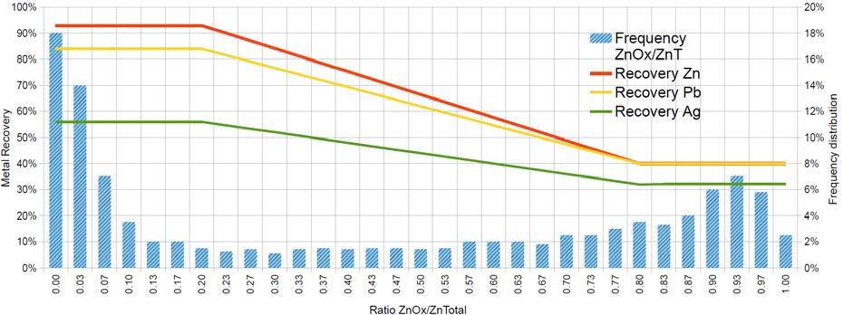
Source: SRK, 2017
Figure 1-1: Florida Canyon Metal Recoveries Relative to ZnO/ZnT Ratio
Anticipated concentrate grades used in cut-off grade calculations are 50% for both zinc and lead concentrates, the latter containing associated silver.
SRK sees opportunities for more advanced test work to optimize the metallurgical flow sheet. Previous test work used conventional procedures that were not specific to Florida Canyon material types. Similarly, fines encountered in previous work were not handled appropriately, resulting in sub-optimal flotation. Sample selection is a key element and more site-specific test work is expected to enhance overall recovery projections at the next level of study.
| 1.6 | Mineral Resource Estimate |
Since the 2013 resource estimate (SRK, 2013), Millpo conducted a considerable amount of resampling and metallurgical test work to determine recoverable sulfide and oxide grades for both zinc and lead to better understand recoverable metal in the deposit. This work led to a change in the definition of oxide, transition, and sulfide domains. In the 2013 model, oxide, transition, and sulfide domains were developed based on core logging and then individual metallurgical recoveries were assigned as to each domain. Following the 2014 metallurgical test work, it was determined that a quantitative approach utilizing the ratio of estimated oxide zinc grade to estimated total zinc grade would provide the best representation of the recoverable resource.
The 2017 resource model was built by Votorantim and validated by SRK. Development of the 2017 resource estimate involved two separate grade estimations. First, primary reporting grades were estimated using the same samples as the 2013 resource estimate. This estimate assigned the grades from which metal quantities were calculated in the resource. A second resource estimate was conducted using the Votorantim 2014 sample program to assign sulfide and oxide grades for both zinc and lead. These grades were used to calculate a zinc oxide to total zinc ratio (ZnOx/ZnT), which was then used to determine if material was oxide, sulfide, or mixed and to assign a recovery to each modeled block based on that ratio.
| 19 |
The Mineral Resource estimate was based on a 3-D geological model of major structural features and stratigraphically controlled alteration and mineralization. A total of 23 mineral domains were interpreted from mineralized drill intercepts, comprised mostly of 1 m core samples. The project is in metric units. Zinc, lead and silver were estimated into model blocks using Ordinary Kriging (OK). Oxide, Sulfide and Mixed material types were determined based on the ZnOx/ZnT ratio. Density was determined from a large percentage (55%) of measured values, which were used to develop equations for density assignment based on rock type and kriged metal content of the samples.
Resources were reported to Measured, Indicated and Inferred classification compliant with CIM definitions according to NI 43-101 guidance. Blocks classified as Measured were estimated by Ordinary Kriging using at least three composites within 25 m in the major and semi-major search directions and 10 m in the minor search direction. Blocks classified as Indicated were estimated by Ordinary Kriging using at least three composites within 50 m in the major and semi-major search directions and 20 m in the minor search direction. Blocks classified as inferred were estimated by Ordinary Kriging using at least two composites within 100 m in the major and semi-major search directions and 40 m in the minor search direction. A fourth category was flagged in the model including blocks estimated beyond the limits above.
SRK validated the Votorantim model using the following criteria:
| · | SRK independent grade estimate compared to the Votorantim grade estimate; |
| · | Visual comparative analysis between composite and block grades; and |
| · | Statistical comparison of global averages of the original composite values and the model estimates. |
SRK concludes that the model is adequate if not slightly conservative for the deposit and is suitable for use in preliminary mine planning.
The Mineral Resource estimate for the Florida Canyon zinc-lead-silver deposit is presented in Table 1-6.
| 20 |
Table 1-6: Mineral Resource Statement for the Florida Canyon Zn-Pb-Ag Deposit, Amazonas Department, Peru, SRK Consulting (U.S.), Inc., July 13, 2017
Zn Eq Contained
|
Category |
Mass (kt) |
Zn Grade | Pb Grade |
Ag Grade |
ZnEq Grade | Zn Contained | Pb Contained | Ag Contained | Zn Eq Contained | ||||
| (%) | (%) | (g/t) | (%) | (kt) | (klb) | (kt) | (klb) | (kg) | (koz) | (kt) | (klb) | ||
| Measured | 1,285 | 13.13 | 1.66 | 19.42 | 14.68 | 169 | 372,200 | 21 | 46,900 | 25,000 | 800 | 189 | 415,900 |
| Indicated | 1,970 | 11.59 | 1.45 | 17.91 | 12.95 | 228 | 503,500 | 29 | 63,200 | 35,300 | 1,130 | 255 | 562,700 |
|
Measured + Indicated |
3,256 |
12.2 |
1.53 |
18.51 |
13.63 |
397 |
875,700 |
50 |
110,100 |
60,300 |
1,930 |
444 |
978,600 |
| Inferred | 8,843 | 10.15 | 1.05 | 13.21 | 11.16 | 898 | 1,978,900 | 93 | 204,900 | 116,900 | 3,760 | 986 |
2,174,80 0 |
Source: SRK, 2017
| · | Mineral Resources are not Mineral Reserves and do not have demonstrated economic viability. There is no certainty that all or any part of the Mineral Resources estimated will be converted into Mineral Reserves. |
| · | Grades reported in this table are "contained" and do not include recovery. |
| · | Mineral resources are reported to a 2.8% recovered zinc-equivalent (RecZnEq%) cut-off grade. |
| o | Assuming the average recoveries for the resource, this corresponds to non-recovered cut-off grade of 3.6% contained ZnEq%. |
| · | RecZnEq% was calculated by multiplying each block grade by its estimated recovery, then applying mining costs, processing costs, general and administrative (G&A) costs, smelting costs, and transportation costs to determine an equivalent contribution of each grade item to the Net Smelter Return. |
| o | Mining costs, processing, G&A, smelting, and transportation costs total US$74.70/t. |
| o | Metal price assumptions were: Zinc (US$/lb 1.20), Lead (US$/lb 1.0) and Silver (US$/oz 17.50), |
| o | As the recovery for each element was accounted for in the RecZnEq%, recoveries were not factored into the calculation of the 2.8% cut-off grade. |
| o | Average metallurgical recoveries for the resource are: Zinc (79%), Lead (72%) and Silver (50%) |
| o | The equivalent grade contribution factors used for calculating RecZnEq% were: (1.0 x recovered Zn%) + (0.807 x recovered Pb%) + (0.026 x recovered Ag ppm). |
| · | The contained ZnEq% grade reported above was calculated by dividing the RecZnEq% grade by the calculated zinc recovery. |
| · | Density was calculated based on material types and metal grades. The average density in the mineralized zone was |
3.01 g/cm3.
| · | Mineral Resources, as reported, are undiluted. |
| · | Mineral Resource tonnage and contained metal have been rounded to reflect the precision of the estimate and numbers may not add due to rounding. |
| 1.7 | Mineral Reserve Estimate |
No Mineral Reserves were estimated as part of this PEA.
| 1.8 | Mining |
Both longhole open stoping with backfill and cut and fill mining methods have been selected for the mine planning work. The mining method selection was based on the mineralization shape, orientation, and the desire to put tailing material underground. Geotechnical assessment of the orebody shape and ground conditions confirmed the mining method selection. The design parameters have been laid out using empirical design methods based on similar case histories. Cut and fill opening sizes are 3 m x 3 m and stopes are 3 m wide x 16 m in height.
An NSR approach was used to calculate the value of a block. Two products will be produced, lead and zinc concentrates. The lead concentrate will contain a payable amount silver. Stope optimization within VulcanTM software was used to determine potentially economically minable material, based on the NSR value and a cut-off of US$42.93 for cut and fill areas, and a cut-off of US$41.40 for longhole areas. The stope optimizer output shapes were visually inspected and isolated blocks (i.e., small blocks far from larger groups of blocks or where additional development is not practical or economically feasible) were removed from the mining block inventory. The resource model was queried against the final stope optimization shapes to determine tonnes and grade of material inside the shapes and mining dilution and recovery factors were applied.
| 21 |
A development layout was created to provide access to the mining levels and to tie levels into ramps. Access to the underground workings will be via three main portals (San Jorge, P01 and P03). An additional portal (P02) will be used primarily for ventilation, and three additional drifts will daylight to facilitate ventilation.
The tonnes and grade of the resource material contained within the mining blocks, adjusted by recovery and dilution, and categorized by the resource classification is provided in Table 1-7. The mine plan resource consists of a total of 11.2 Mt with an average grade of 8.34% Zn, 0.90% Pb, and
11.3 g/t Ag and is made up of Measured, Indicated, and Inferred material. Estimated average dilution, processing recoveries and the ZnOx/ZnT ratio is also provided in Table 1-8.
Table 1-7: Mine Plan Resource for the Florida Canyon Zn-Pb-Ag Deposit, Amazonas Department, Peru, SRK Consulting (U.S.), Inc., July 21, 2017
|
Category |
Mass | Zn Grade | Pb Grade | Ag Grade | NSR * |
ZnEq ** |
Zn Contained | Pb Contained | Ag Contained | ZnEq ** Contained |
| (kt) | (%) | (%) | (g/t) | (US$/t) | (%) | (kt) | (kt) | (kg) | (kt) | |
| Measured | 1,293 | 10.64 | 1.33 | 15.60 | 197.12 | 12.38 | 138 | 17 | 20,157 | 160 |
| Indicated | 2,011 | 8.77 | 1.08 | 13.44 | 166.85 | 10.22 | 176 | 22 | 27,026 | 206 |
| M&I | 3,303 | 9.51 | 1.18 | 14.28 | 178.69 | 11.05 | 314 | 39 | 47,182 | 365 |
| Inferred | 7,883 | 7.86 | 0.78 | 10.07 | 135.36 | 9.03 | 619 | 62 | 79,354 | 712 |
| Total Mine Design |
11,187 |
8.34 |
0.90 |
11.31 |
148.16 |
9.66 |
933 |
101 |
126,536 |
1,081 |
Source: SRK, 2017
* NSR is calucalted using variable recoveries based on sulfide/oxide ratios (recovery ranging from 32%-93%), a Zn price of US$1.20/lb, a Pb price of US$1.00/lb, an Ag price of US$17.50/oz. The transportation charge is US$70.00/t conc, Zn treatment charge of US$115/t conc, Pb treatment charge of US$100/t conc, Zn refining charge of US$0.115/lb Zn, and Pb refining charge of US$0.1/lb Pb. These factors were used for mine planning and vary somewhat from the final economic model.
** ZnEq estimate is based on a NSR value of US$19.62 per 1% Zn. The US$19.62 is calculated using a Zn price of US$1.20/lb, a Pb price of US$1.00/lb, an Ag price of US$17.50/oz. The ZnEq also includes TC/RC and transportation costs and assumes an average Zn recovery of 78.15% which differs somewhat from that presented in the economic model. An example of the NSR to ZnEq calculation is (148.16/19.62)/0.7815.
Table 1-8: Mine Plan Resource Average Process Recovery
| Process Recovery | |||||
| Ag (%) | Pb (%) | Zn (%) | ZnOx/ZnT Ratio | Dilution | |
| Mine Plan Resource | 51.7 | 74.3 | 79.8 | 0.26 | 34% |
Source: SRK, 2017
The PEA is preliminary in nature, that it includes Inferred Mineral Resources that are considered too speculative geologically to have the economic considerations applied to them that would enable them to be categorized as Mineral Reserves, and there is no certainty that the PEA will be realized. Mineral Resources that are not Mineral Reserves do not have demonstrated economic viability.
A production schedule was generated using iGantt software. The schedule targeted a production rate of 2,500 t/d (912,500 mineralized tonnes per year).
| 22 |
| 1.9 | Recovery Methods |
Given the location of the deposit, it is anticipated three underground portals will be producing mineralized material at any given time. Because of the challenging topography and road conditions, trucking Run-of-Mine (ROM) mineralized material would demand a lengthy route from the underground portals to the plant’s location. Instead, SRK has designed a set of conventional overland conveyors with a maximum slope of 20° to simplify the operation and significantly reduce the cost of transferring mineralized material from the mine portals to the process plant. A portable, primary jaw crusher is to be installed at each underground mine portal to ensure the ROM is adequately sized for the conveying system.
Florida Canyon mineralized material will be processed using a conventional concentration plant consisting of three stage crushing, grinding using a single-stage ball mill to 80% minus 44 microns, and differential flotation to produce two final products: a zinc concentrate and a lead concentrate containing payable silver. The concentrate will be truck transported to the point of sale. Tailings will be used as backfill or filtered and conveyed to a dry stack tailings storage facility.
The mill will process 2,500 t/d of fresh mineralized material, and produce approximately 287 t of zinc concentrate grading 50% Zn, 1% Pb, and 0.6 g/t Ag and approximately 46 t of lead concentrate grading 50% Pb, 8.4 g/t Ag, and 6% Zn.
The power requirements for the projected milling operation is estimated at maximum 3.5 MW. Power for milling operations will be supplied by a third-party as line power at an estimated cost of US$0.084/kWh. The water requirement for the mill at a capacity of 2,500 t/d is estimated at maximum 20 liters per second. Water for processing will be acquired from surface water sources and as recycled water from tailings dewatering operations. Reagents and grinding balls, will be supplied by road from Pedro Ruiz and stored locally.
There are potential synergies for processing oxide mineralization at Florida Canyon using expertise that Votorantim has gained at the Vazante and Morro Agudo mines in Brazil. These other existing operations have demonstrated success recovering hemimorphite, smithsonite, and hydrozincite, which may improve future recovery projections for Florida Canyon.
| 1.10 | Project Infrastructure |
Florida Canyon is a greenfield project with no substantive existing infrastructure. The communities in the region are small and cannot support the operation from an infrastructure standpoint so a camp will be required. The infrastructure requirements for the Project will include an upgrade to the existing 26 km access road and the construction of an additional 24 km of support roads for access to mine portals, plant, and other infrastructure.
Site facilities will include the processing plant, mine, crushers and conveyors for ore/waste transportation, mine backfill systems including a paste backfill plant and cemented rock fill plant, water supply piping and tank, a dry stack TSF, 400 person camp, septic system, potable water treatment system, site power distribution, health/safety environmental office, mine office, mine dry, rescue and first aid building, security gate house, truck scale, truck wash, laboratory, incinerator system, fuel storage and pumping system.
| 23 |
Makeup water for the processing plant will be supplied from a local creek through a piping system to a storage tank that will also provide fire system water. The majority of the water requirements will be provided by rainfall and recycle water from the dry stack tailings storage facility (TSF) returned to the processing plant facility. A third-party will supply line power through a hydroelectric power generator, transmission line, and substation owned by the third party with costs recovered through an electricity surcharge over the life of the Project. Zinc concentrate will be transported by 30 t over the road trucks to the Votorantim Cajamarquilla smelter near Lima. Lead concentrate will be trucked to the Port of Callao near Lima, and shipped to an overseas lead smelter.
| 1.11 | Environmental Studies and Permitting |
Environmental permits for mineral exploration programs are divided into two classes. Class I permits allow construction and drilling for up to 20 platforms with a maximum disturbance of 10 ha. A Class II permit provides for more than 20 drill locations or for a disturbance area of greater than 10 ha. Votorantim has filed applications for and received Class II permits for various phases of the Project and has filed and received the required associated permits.
Permitting requirements for mining include an Estudio de Impacto Ambiental (EIA) that describes in detail the mining plan and evaluates the impacts of the plan on environmental and social attributes of the property. Baseline studies include air quality, surface and groundwater quality, flora and fauna surveys, archeological surveys and a study of the social conditions of the immediate property and an area of interest that includes local communities. Public meetings are required in order that local community members can learn about and comment on the proposed operation. Many of the baseline studies required for mining have been completed by Votorantim.
| 1.12 | Conclusions and Recommendations |
1.12.1 General
The Florida Canyon Zinc Project is a significant greenfields potentially underground mineable high- grade zinc deposit containing associated lead and silver. The Project has a large land position and strong technical and financial backing through Solitario’s earn-in JV partner Votorantim. While this document represents the first formal economic evaluation of the Project, Votorantim and Cominco report having previously spent over US$60 million on drilling, test work and strategic planning for development (Solitario, 2014). Current projections in the zinc metal market suggest a near-term reduction in zinc supply as current major producers exhaust reserves.
SRK’s site visit to the project on the ground in northern Peru found it to be a well-organized facility, with current QA/QC protocols in place for drilling data verification and validation. Material handling, core storage and security were all at or above industry standards.
SRK used a number of methods to validate the Votorantim resource block model starting with a face-to-face meeting with the modeler and following on with a thorough audit of the model source data, geologic modeling techniques, grade and tonnage estimation methods and classification protocols. SRK found these to be in line with industry standards, having been produced with recognized mining software, defensible data and reasonable assumptions. SRK was able to independently validate the model results.
A significant component of the SRK input to this PEA was the development of the underground mine plan. Because Florida Canyon is a polymetallic zinc-lead-silver deposit, each model block in the mine model was evaluated on an NSR basis, which included an estimate of recovery. Recovery was developed from a robust 2014 metallurgical campaign that characterized all expected material types. A recovered grade by block was used to build the underground stoping plan, complete with access, ventilation and an assessment of mine recovery and dilution.
| 24 |
SRK is unaware of any environmental, permitting, legal, title, taxation or marketing factors that could limit or affect the resource stated in this document. The project will benefit from additional infill and exploration drilling, additional process-metallurgical test work, detailed engineering studies for infrastructure and tailings management and forward planning to clearly define concentrate transport and smelter costs.
1.12.2 Mineral Resource Estimate
The current exploration model for the Project has been applied successfully in drillhole planning and resource definition. There is low risk to the Project if no additional exploration is completed. However, additional drilling for resource definition has a strong potential to expand the known resource extent and upgrade Inferred resources to Measured and Indicated. The most prospective targets include:
| · | Extension drilling south of the San Jorge zone and northeast of the Karen-Milagros zones are considered the highest priority to increase high-grade zinc sulfide mineralization. Both zones are open in the recommended areas of drill testing; |
| · | Infill drilling several large un-drill tested areas surrounded by mineralized zones within the mineralized footprint has the potential to significantly increase resources; |
| · | Extension drilling peripheral to the currently defined mineralized footprint; and |
| · | Further develop drill targets over the 20 km long northern Florida Canyon mineralized corridor where large areas of strong zinc in soil and rock chip geochemistry indicate the potential for additional mineralized zones. |
At present, the deposit is open laterally to the north and south as well as to the west and east on the downthrown sides of the horst that defines the limits of exploration to date. Gaps in the drill pattern within the footprint of the existing drilling provide another opportunity to increase resources where drill spacing limits the continuity of stratigraphically controlled mineralization. A constraint on effective exploration and delineation drilling in these areas is the access to drilling stations due to the rugged terrain. The completion of a road into the area will help to expedite future drilling and development programs by providing increased access and lowering costs.
The discovery of the high-angle, high-grade San Jorge zone has prompted more emphasis on angled drilling, where most of the historic drilling is vertical to near-vertical and is therefore ineffective at locating and defining near-vertical structures. These “break-through” structures have been mapped on surface in several locations, but due to logistical constraints, have not been adequately drill tested for their down-dip continuity. Similarly, there appear to be additional drill targets at the intersection of the high-angle structures and the flat manto zones, where grades are locally enhanced. These concentrations may be present within the existing drilling footprint, but require additional drilling to delineate. The high grade and potential tonnage of such targets provide an incentive to locate and further define resources of this geometry.
| 25 |
1.12.3 Mineral Processing and Metallurgical Testing
Processing of sulfide mineralization (zinc-lead-silver) from the Florida Canyon deposit is straight forward using conventional flotation to a concentrate followed by offsite smelting. Producing a commercial quality zinc concentrate from mixed material needed to incorporate Dense Media Separation methods (DMS) in order to maintain high recoveries (80+%). A conventional flotation approach reached commercial quality (about 50% Zn) at the expense of lower metal recovery, with a similar outcome for the lead concentrate. It is SRK’s opinion that conventional flotation should be able to achieve enhanced commercial level results (grade and recovery) under improved crushing, grinding, and flotation conditions.
Available information about silver is very limited. The laboratory developed a relationship between lead's head grade and silver grade in the final lead concentrate. This relationship follows what is typically observed in this type of deposit, therefore as this stage of development it is assumed to be valid, but SRK recommends confirming it in the next testing phase of the project.
To optimize recovery and grade when attempting to reach separation of the zinc and lead minerals into their respective commercial quality concentrates, SRK recommends approaching the selection of samples for the next phase of metallurgical sampling and testing:
| · | The core logging needs to incorporate attributes like clay percent, clay type, RQD, oxide content, sulfide content; |
| · | Assaying of the core should include whole rock analysis; and |
| · | Collect samples for metallurgical testing representing distinctive zones in the deposit. Grade variability should be secondary criteria when selecting samples, but they must be reasonably close to what a potential mining operation would be able to deliver to the mill. |
1.12.4 Mineral Reserve Estimate
There were no Mineral Reserves estimated for this PEA.
1.12.5 Mining Methods
Depending upon the geometry of the mineralized zones, SRK selected longhole stoping to be used in steeply dipping zones and mechanized drift-and-fill extraction methods in shallowly dipping mantos. Conventional room and pillar mining on a checkerboard pattern could be applied to specific zones of the Florida Canyon project, particularly in lower grade areas, and should be considered in future trade- off studies at the prefeasibility level. Cemented paste backfill will be placed underground to increase mining recovery and to stabilize mined-out areas. Adits will provide access from the surface to the mineralized zones currently defined in the mine plan.
Sub-level open stoping parameters for this study were based on empirical relations from case histories. As the project advances, additional geotechnical stability modeling using numerical methods is recommended. Karst topography is prevalent in the district and karst caverns were encountered during the excavation of the San Jorge Adit. Additional geotechnical and hydrogeological evaluation of this condition is required to ensure safe operating conditions in the underground mining. A crown pillar of 30 m has been used for planning. This assumption should be reevaluated in future work. Overall, a cost-benefit analysis of ground support, dilution, mine recovery, and ventilation should be undertaken at the next level of study.
Operating costs, which ultimately define NSR value and drive stope designs, were developed from benchmarks, analogous projects in the region, and commercial cost sources. SRK recommends a revision of these costs from first principles as the project advances.
| 26 |
SRK notes that there are likely opportunities to improve the production schedule. Opportunities include improved sequencing of high grade material and, potentially, a decrease in the pre-production timeframe. A more detailed design and schedule with corresponding trade-off studies, as well as more detailed construction timeframe estimates, would be required for the next phase of study.
1.12.6 Recovery Methods
The Florida Canyon polymetallic zinc-lead-silver deposit can be processed using a conventional concentration plant consisting of three-stage crushing, grinding using ball mill, and differential flotation to produce two final products: a zinc concentrate and a lead concentrate. Detailed sizing and costing of the processing plant components will follow additional metallurgical testing proposed in this study. Power supply and water supply appear to be fairly well defined for the project, though additional studies may be needed to refine these services and the costs of these services to the project.
1.12.7 Project Infrastructure
The Florida Canyon deposit is located in steep terrain in a remote part of northern Peru with moderate to high rainfall. These geographic and climatic conditions pose challenges to both access and infrastructure development.
As presently understood, the key support services of power supply and water supply are available and part of a district-wide infrastructure improvement campaign being implemented by the Peruvian government and related third-party providers. The most significant advancement in the infrastructure investigation for the PEA was identifying the probability of hydroelectric power distribution to the site, as a lower cost alternative to on-site power generation. Water supply for operations appears to be straight forward, with abundant surface water available for mineral processing and camp support.
The infrastructure component with the largest footprint and projected cost is the tailings storage facility. As part of this study, SRK has evaluated this as a dry stack facility in order to achieve geotechnical stability and reduce the area requiring reclamation. Trade-off studies are warranted to optimize moisture content, binding characteristics, and placement and compaction methods during tailings placement.
1.12.8 Environmental Studies and Permitting
Additional environmental baseline studies are required for further project development.
Impact to groundwater is expected to be minimal as underground surface exposures are minor and future exposed sulfides are not acid generating. There are no groundwater wells required for processing or potable water supply. There will be little or no surface area disturbance related to waste rock placement.
Tailings are predicted to have low amounts of iron sulfide and to be geochemically stable with respect to acid rock drainage. There is also substantial neutralization capacity in the carbonate host rocks to mitigate acid generation. Residual lead and zinc sulfides have low acid-generating capacity; however, they are subject to metal leaching and therefore require compaction during placement.
SRK recommends in future studies to design the tailings surface and spillway stormwater structure and evaluate options to reduce or eliminate the long-term obligation for monitoring and maintenance.
| 27 |
1.12.8 Recommendations – Work Programs and Costs
SRK acknowledges, after examination of the Project data set, that there have been a significant number of technical studies completed by Votorantim, many of which are beyond PEA. Therefore, the work elements listed in Table 1-9 represent mostly prefeasibility and feasibility level engineering and drilling to support those studies.
At the juncture where prefeasibility level engineering has been completed, the Project will likely warrant further public reporting to an international standard (JORC, or NI 43-101). Technical information required to achieve this level of project development are listed in Table 1-9. A cost estimate for these work elements is included in the table.
Table 1-9: Summary of Costs for Recommended Work
| Work Program | Estimated | Assumptions/Comments |
| Engineering Studies | Cost US$ | |
| Metallugical variability and recovery optimization test work | 500,000 | Commercial Laboratory |
| Prefeasibility Study (PFS) and Trade-off Studies | 600,000 | Votorantim or consultant engineer |
| Subtotal Studies | $1,100,000 | |
| Drilling | Salaried new hire or contract PM | |
| Exploration Drilling | 2,100,000 | 20 holes to 350 m at US$300/m |
| Resource Conversion Drilling | 2,100,000 | 20 holes to 350 m at US$300/m |
| Metallurgical Drilling for Flotation and Comminution | 1,225,000 | 10 PQ holes to 350 m at US$350/m |
| Geotechical Drilling for Mining | 500,000 | 10 holes oriented to 100 m at US$500/m |
| Geotechnical Drilling for Foundation Stability | 225,000 | 50 holes to 30 m at US$150/m |
| Hydrogeological Drilling | 600,000 | 4 holes to 300 m at US$500/m |
| Subtotal Drilling | $6,750,000 | |
| Studies + Drilling | 7,600,000 | |
| Contingency at 15% | 1,435,000 | |
| Total | $9,285,000 |
Source: SRK, 2017
| 28 |
| 2 | Introduction |
| 2.1 | Terms of Reference and Purpose of the Report |
This report was prepared as a National Instrument 43-101 (NI 43-101) Technical Report, Preliminary Economic Assessment (Technical Report or PEA) by SRK Consulting (U.S.), Inc. (SRK), with Votorantim Metais Holding S.A. (Votorantim) with Solitario Zinc Corp. (Solitario), (collectively, owners) on the Florida Canyon Zinc Project located in Amazonas Department, Peru (Florida Canyon or Project). The Project name was changed in 2017 from Bongará, as it was called previously, to Florida Canyon. Some of the figures in this report still reference Bongará. The reader is advised to use Bongará interchangeably with Florida Canyonwhen reviewing those figures.
This study represents the advancement of the Project from a 2014 Technical Report on Resources, to this 2017 PEA. Highlights of this PEA include a thirteen-year life-of-mine underground mine plan, comminution and flotation of zinc and lead concentrates with at a production rate of 2,500 t/d followed by dry-stack tailings storage. Site infrastructure includes line power to the site, water distribution systems, a townsite and access roads for construction and re-supply as well as for zinc concentrate transport to a point of sale at the Cajamarquilla smelter.
The quality of information, conclusions, and estimates contained herein is consistent with the level of effort involved in SRK’s services, based on: i) information available at the time of preparation, ii) data supplied by outside sources, and iii) the assumptions, conditions, and qualifications set forth in this report. This report is intended for use by the owners subject to the terms and conditions of its contract with SRK and relevant securities legislation. The contract permits the owners to file this report as a Technical Report with Canadian securities regulatory authorities pursuant to NI 43-101, Standards of Disclosure for Mineral Projects. Except for the purposes legislated under provincial securities law, any other uses of this report by any third party is at that party’s sole risk. The responsibility for this disclosure remains with the issuing companies. The user of this document should ensure that this is the most recent Technical Report for the property as it is not valid if a new Technical Report has been issued.
The PEA is preliminary in nature, that it includes Inferred Mineral Resources that are considered too speculative geologically to have the economic considerations applied to them that would enable them to be categorized as Mineral Reserves, and there is no certainty that the PEA will be realized. Mineral Resources that are not Mineral Reserves do not have demonstrated economic viability.
This report provides Mineral Resources, and a classification of resources prepared in accordance with the Canadian Institute of Mining, Metallurgy and Petroleum Standards on Mineral Resources and Reserves: Definitions and Guidelines, May 10, 2014 (CIM, 2014).
| 2.2 | Qualifications of Consultants (SRK) |
The Consultants preparing this technical report are specialists in the fields of geology, exploration, Mineral Resource and Mineral Reserve estimation and classification, underground mining, geotechnical, environmental, permitting, metallurgical testing, mineral processing, processing design, capital and operating cost estimation, and mineral economics.
The following individuals, by virtue of their education, experience and professional association, are considered Qualified Persons (QP) as defined in the NI 43-101 standard, for this report, and are members in good standing of appropriate professional institutions. QP certificates of authors are provided in Appendix A. The QP’s are responsible for specific sections as follows:
| 29 |
| · | Walter Hunt, CPG, an employee of Solitario, is the QP responsible for Sections 2, 4 and parts of 20; |
| · | J.B. Pennington, CPG is the QP responsible for Sections 5-10, 12, 14, 23, 24 and part of 1, 20, 25, and 26; |
| · | Joanna Poeck, PE, MMSA is the QP responsible for Sections 15-16 and part of 1, 25 and 26; |
| · | Jeff Osborn BEng Mining, MMSA is the QP responsible for Section 18-19, 21-22 and part of 1, 25 and 26; |
| · | Daniel Sepulveda, RM-SME is the QP responsible for Sections 13, 17, the capital and operating cost for processing in Section 21, and part of 1, 25 and 26; and |
| · | James Gilbertson, CGeol is the QP responsible for Section 11, the site visit, inspection of geological sampling and data collection practices, and review of resource estimation practices. |
| · | John Tinucci, PhD, PE is the QP responsible for Section 16.2. |
| 2.3 | Details of Inspection |
James Gilbertson, C. Geol., of SRK Exploration Services (U.K.), visited the Florida Canyon Project site and core storage facility in Shipasbamba, Peru on May 5 to 7, 2014. This trip included a follow-up visit to Votorantim’s Lima, Peru office on May 9, 2014. Mr. Gilbertson is a Chartered Geologist in the Geological Society of London, and a Qualified Person in the discipline of resource geology, according to NI 43-101 requirements.
| 2.4 | Sources of Information |
The sources of information include data and reports supplied by Solitario personnel and representatives of Votorantim, as well as documents cited throughout the report and referenced in Section 27.
| 2.5 | Effective Date |
The effective date of this report is July 13, 2017.
| 2.6 | Units of Measure |
The metric system has been used throughout this report. Tonnes are metric of 1,000 kg, or 2,204.6 lb. All currency is in U.S. dollars (US$) unless otherwise stated.
| 30 |
| 3 | Reliance on Other Experts |
The Consultants used their experience to determine if the information from previous reports was suitable for inclusion in this technical report and adjusted information that required amending. This report includes technical information, which required subsequent calculations to derive subtotals, totals and weighted averages. Such calculations inherently involve a degree of rounding and consequently introduce a margin of error. Where these occur, the Consultants do not consider them to be material.
Items such as mineral titles and agreements have not been independently reviewed by SRK and SRK did not seek an independent legal opinion of these items.
| 31 |
| 4 | Property Description and Location |
| 4.1 | Property Location |
The Florida Canyon Zinc Project (the Project, formerly called Bongará) is located in the Eastern Cordillera of Peru at the sub-Andean front in the upper Amazon River Basin. It is within the boundary of the Shipasbamba community, 680 km north-northeast of Lima and and 245 km northeast of Chiclayo, Peru, in the District of Shipasbamba, Bongará Province, Amazonas Department (Figure 4-1). The Project area can be reached from the coastal city of Chiclayo by the paved Carretera Marginal road. The central point coordinates of the Project are approximately 825,248 East and, 9,352,626 North (UTM Zone 17S, Datum WGS 84). Elevation ranges from 1,800 masl to approximately 3,200 masl. The climate is classified as high altitude tropical jungle in the upper regions of the Amazon basin. The annual rainfall average exceeds 1 m with up to 2 m in the cloud forest at higher elevations.
| 32 |
Source: Votorantim, 2013b
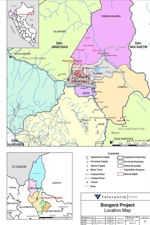
Figure 4-1: Project Location Map
| 33 |
| 4.2 | Mineral Titles |
Florida Canyonis a mineral exploration project comprised of sixteen contiguous mining concessions covering approximately 12,600 ha (Table 4-1). The concession titles are in the name of Minera Bongará and are subject to the Minera Bongará joint venture agreement between Solitario and Votorantim. All of these concessions are currently titled.
The Minera Bongará concessions are completely enveloped by a second group of thirty-seven contiguous mining concessions, covering approximately 30,700 ha (Table 4-2). The concession titles are in the name of Minera Chambara. Of the thirty-seven concessions, twelve titles are pending. Claim areas are shown in Figure 4-2.
According to Peruvian law, concessions may be held indefinitely, subject only to payment of annual fees to the government. At the time of this study, concession payments were current for Minera Bongará claims, with 2017 fees of US$122,600 (Table 4-1). The fees for Minera Chambara total US$140,530 and these fees do not include the additional nine Charlita claims filed in January, 2017, which are still pending (Table 4-2). Minera Chambara, a Peruvian company also subject of a separate joint venture agreement between Votorantim and Solitario, holds mineral concessions surrounding the Minera Bongará claims but which do not contain any of the resources subject of this economic analysis.
Votorantim, who has served as operator of the joint venture company Minera Bongará, entered into a surface rights agreement with the local community of Shipasbamba which controls the surface rights of the Project. This agreement provides for annual payments and funding for mutually agreed upon social development programs in return for the right to perform exploration work including road building and drilling.
| 34 |
Table 4-1: List of Minera Bongará Mineral Claims
| Concession Name | Number | Status | Hectares | Claim Date | 2017 Holding Fees (US$) | District |
| BONGARA CINCUENTICINCO | 10233396 | Titled | 1,000 | 8/7/1996 | 23,000.00 | FLORIDA/SHIPASBAMBA |
| BONGARA CINCUENTICUATRO | 10233296 | Titled | 600 | 8/7/1996 | 13,800.00 | FLORIDA/SHIPASBAMBA |
| BONGARA VEINTISIETE | 10783595 | Titled | 300 | 6/26/1995 | 6,900.00 | SHIPASBAMBA |
| DEL PIERO UNO | 10338505 | Titled | 1,000 | 11/2/2005 | 9,000.00 | FLORIDA/SHIPASBAMBA |
| DEL PIER DOS | 10338405 | Titled | 600 | 11/2/2005 | 5,400.00 | FLORIDA/SHIPASBAMBA |
| DEL PIERO TRES | 10338605 | Titled | 700 | 11/2/2005 | 6,300.00 | FLORIDA/SHIPASBAMBA |
| DEL PIERO CUATRO | 10000206 | Titled | 500 | 1/3/2006 | 4,500.00 | FLORIDA/SHIPASBAMBA |
| DEL PIERO CINCO | 10000306 | Titled | 1,000 | 1/3/2006 | 9,000.00 | SHIPASBAMBA |
| DEL PIERO SEIS | 10204507 | Titled | 1,000 | 3/23/2007 | 9,000.00 | CAJARURO/FLORIDA |
| VM 42 | 10190507 | Titled | 1,000 | 3/21/2007 | 9,000.00 | CAJARURO/FLORIDA/ SHIPASBAMBA |
| VM 74 | 10193707 | Titled | 1,000 | 3/21/2007 | 9,000.00 | SHIPASBAMBA |
| VM 75 | 10193807 | Titled | 1,000 | 3/21/2007 | 9,000.00 | SHIPASBAMBA |
| VM 94 | 10045708 | Titled | 900 | 1/28/2008 | 2,700.00 | FLORIDA/SHIPASBAMBA |
| VM 95 | 10045808 | Titled | 500 | 1/28/2008 | 1,500.00 | FLORIDA |
| VM 97 | 10046008 | Titled | 1,000 | 1/28/2008 | 3,000.00 | FLORIDA/SHIPASBAMBA |
| VM 98 | 10046108 | Titled | 500 | 1/28/2008 | 1,500.00 | FLORIDA/SHIPASBAMBA |
| Total | $122,600.00 |
Source: Solitario, 2017
| 35 |
Table 4-2: List of Minera Chambara Mineral Claims
| Concession Name | Number | Status | Hectares | Claim Date | 2017 Holding Fees (US$) | District |
| ANGIE KAROLL TRES | 10387906 | Titled | 900 | 1/3/2006 | 8,100.00 | CAJARURO |
| ANGIE KAROLL CUATRO | 10388106 | Titled | 300 | 1/3/2006 | 2,700.00 | CAJARURO |
| BONGARA VEINTIDOS M | 10053315 | Titled | 1000 | 1/5/2015 | 3,000.00 | CAJARURO/ YAMBRASBAMBA |
| BONGARA VEINTITRES M | 10053215 | Titled | 671.9322 | 1/5/2015 | 2,015.80 | YAMBRASBAMBA |
| CAROLINA 1 M | 10106114 | Title Pending | 500 | 1/2/2014 | 1,500.00 | YAMBRASBAMBA |
| CAROLINA 2 M | 10106014 | Titled | 500 | 1/2/2014 | 1,500.00 | FLORIDA/ YAMBRASBAMBA |
| CHARITO 2007 | 10199807 | Titled | 1000 | 3/23/2007 | 9,000.00 | CAJARURO/ SHIPASBAMBA |
| DEL PIERO SIETE | 10205907 | Titled | 1000 | 3/23/2007 | 9,000.00 | CAJARURO/ YAMBRASBAMBA |
| DEL PIERO OCHO | 10205807 | Titled | 1000 | 3/23/2007 | 9,000.00 | CAJARURO/ YAMBRASBAMBA |
| MINA 4 M | 10052215 | Titled | 300 | 1/5/2015 | 900.00 | CAJARURO |
| SAN JOSECITO M | 10052015 | Title Pending | 1000 | 1/5/2015 | 3,000.00 | CAJARURO/ YAMBRASBAMBA |
| TIA VIOLETA M | 10113114 | Title Pending | 1000 | 1/2/2014 | 3,000.00 | YAMBRASBAMBA |
| VIOLETA 1 M | 10113214 | Titled | 1000 | 1/2/2014 | 3,000.00 | FLORIDA/ YAMBRASBAMBA |
| VM 29 | 10189207 | Titled | 1000 | 3/21/2007 | 9,000.00 | CAJARURO |
| VM 30 | 10189307 | Titled | 1000 | 3/21/2007 | 9,000.00 | CAJARURO |
| VM 33 | 10189707 | Titled | 1000 | 3/21/2007 | 9,000.00 | CAJARURO |
| VM 34 | 10189607 | Titled | 1000 | 3/21/2007 | 9,000.00 | CAJARURO |
| VM 36 | 10190107 | Titled | 1000 | 3/21/2007 | 9,000.00 | CAJARURO |
| VM 37 | 10189907 | Titled | 1000 | 3/21/2007 | 9,000.00 | CAJARURO |
| VM 39 | 10190207 | Titled | 1000 | 3/21/2007 | 9,000.00 | CAJARURO/JAMALCA |
| VM 40 | 10190407 | Titled | 1000 | 3/21/2007 | 9,000.00 | CAJARURO/JAMALCA/ SHIPASBAMBA |
| VM 96 | 10045908 | Titled | 271.4725 | 1/28/2008 | 814.42 | FLORIDA |
| VM 99 | 10046208 | Titled | 244.745 | 1/28/2008 | 734.24 | FLORIDA/ SHIPASBAMBA |
| VM 100 | 10046308 | Titled | 1000 | 1/28/2008 | 3,000.00 | JAZAN/ SHIPASBAMBA |
| VM 101 | 10046408 | Titled | 1000 | 1/28/2008 | 3,000.00 | JAZAN/SANJERONIMO/ SHIPASBAMBA |
| VM 102 | 10046508 | Titled | 600 | 1/28/2008 | 1,800.00 | SANJERONIMO/ SHIPASBAMBA |
| VM 133 | 10134708 | Titled | 600 | 2/6/2008 | 1,800.00 | JAZAN/ SHIPASBAMBA |
| VM 311 | 10099610 | Titled | 555.282 | 2/1/2010 | 1,665.85 | FLORIDA/ YAMBRASBAMBA |
| CHARLITA 5B M | 10049017 | Title Pending | 600 | 1/2/2017 | 0.00 | FLORIDA/ YAMBRASBAMBA |
| CHARLITA 5A M | 10049117 | Title Pending | 800 | 1/2/2017 | 0.00 | FLORIDA/ YAMBRASBAMBA |
| CHARLITA 4 M | 10049217 | Title Pending | 1000 | 1/2/2017 | 0.00 | FLORIDA/ YAMBRASBAMBA |
| CHARLITA 3 M | 10049317 | Title Pending | 1000 | 1/2/2017 | 0.00 | CAJARURO/FLORIDA/ YAMBRASBAMBA |
| CHARLITA 2 M | 10049417 | Title Pending | 1000 | 1/2/2017 | 0.00 | CAJARURO/FLORIDA/ YAMBRASBAMBA |
| 36 |
| Concession Name | Number | Status | Hectares | Claim Date | 2017 Holding Fees (US$) | District |
| CHARLITA 1B M | 10049517 | Title Pending | 900 | 1/2/2017 | 0.00 | CAJARURO/ YAMBRASBAMBA |
| CHARLITA 1A M | 10049617 | Title Pending | 1000 | 1/2/2017 | 0.00 | CAJARURO/ YAMBRASBAMBA |
| BONGARA 60A M | 10049717 | Title Pending | 1000 | 1/2/2017 | 0.00 | YAMBRASBAMBA |
| BONGARA 57 M | 10049817 | Title Pending | 1000 | 1/2/2017 | 0.00 | YAMBRASBAMBA |
| Total | $140,530.30 |
Source: Solitario, 2017
| 37 |
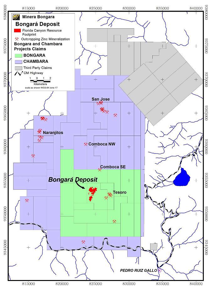 Source: Solitario2017
Figure 4-2: Map of Mineral Claims
| 38 |
4.2.1 Nature and Extent of Issuer’s Interest
Bongará
The Project is controlled by Minera Bongará S.A., and is subject to a joint venture agreement between Votorantim and Solitario since 2006. Votorantim is the operator of the Project and is responsible for keeping the property in good standing. Current ownership is 39% Solitario, 61% Votorantim. Votorantim will earn a 70% interest in Minera Bongará by continuing to fund all project expenditures through a feasibility study with no payback by Solitario. Votorantim is required to offer a loan facility at market rates for repayment of Solitario’s portion of construction capital. Solitario repays the loan through 50% of its project cash flow.
On August 15, 2006, an Agreement Letter was signed between Solitario, Minera Bongará and Votorantim Metais. The Letter defined the commitment of Votorantim to fund US$1.0 million in an annual mineral exploration program, which began in late October 2006.
On March 24, 2007, a definitive agreement superseding the Letter Agreement was signed between the Companies. This definitive agreement (Agreement) provides that the project interest owned by Votorantim and Solitario will be held through the ownership of shares in the joint operating company Minera Bongará , which controls 100% of the mineral rights and assets of the project.
Chambara
Current Chambara Ownership is 85%/15% Solitario/Votorantim. Votorantim may increase their interest to 49% of Minera Chambara by completing cumulative expenditures of US$6.25 million. Votorantim may further increase their interest to 70% by funding a feasibility study and providing a loan for Solitario’s 30% of construction capital. Solitario will repay the loan through 80% of its cash flow from production.
4.2.2 Property and Title in Peru
Mining in Peru is governed by the General Mining Law, which specifies that all mineral assets belong to the federal government. Mining concessions granted to individuals or other entities authorize the title holder to perform all minerals related activates from exploration to exploitation and, once titled, are irrevocable for so long as the fees are paid to the federal government on time. A provisional claim is applied for and title is granted if no other claim exists over the same area. A claim can only be granted in multiples of a quadricula, which is a 100 ha plot, up to a maximum size of 1,000 ha. No monumentation of the claim boundary in the field is necessary.
Annually a payment of US$3.00/ha (US$1.00 for a “small miner”) must be made by the 30th of June or the first business day thereafter to the Ministry of Energy and Mines (MEM) or the claim is automatically forfeited. Any claim not in commercial production exceeding a pro-rated average of US$100/ha for any year after the sixth anniversary incurs a penalty payment of US$6.00 added to the annual payment. If, by the 12th anniversary, commercial production has not been achieved then the penalty increases to US$20.00. The penalties are waived if the title holder shows that investments for each claim exceed ten times the value of the penalty for any given year.
Concessions are real assets and are subject to laws of private property. Foreign entities have the same rights as Peruvians to hold claims except for a zone within 50 km of international borders. Title holders have a right of access and development of minerals but an agreement is required with private property surface rights owners and formalized “Communities”. To ratify an agreement with a Community a majority of all members must vote in favor of the agreement as written. A recently issued law (as modified) also requires formal consultation with indigenous tribes in certain areas.
| 39 |
| 4.3 | Royalties, Agreements and Encumbrances |
Peru imposes a sliding scale net smelter return royalty (NSR) on all precious and base metal production of 1% on all gross proceeds from production up to US$60,000,000, a 2% NSR on proceeds between US$60,000,000 and US$120,000,000 and a 3% NSR on proceeds in excess of US$120,000,000. No other royalty encumbrances exist for the Project.
Corporate income tax in Peru is charged at a flat rate of 30%. However, mining companies must also pay an additional tax varying from 2 to 8.4% of net operating profit.
| 4.4 | Environmental Liabilities and Permitting |
4.4.1 Required Exploration Permits and Status
Environmental permits for mineral exploration programs are divided into two classes. Class I permits allow construction and drilling for up to 20 platforms with a maximum disturbance of 10 ha. A Class II permit provides for more than 20 drill locations or for a disturbance area of greater than 10 ha.
Class I permits require little more than a notification process for approval. Class II drilling permits require an environmental impact declaration (DIA), a permit for harvesting trees (if applicable), an archeological survey report (CIRA), a water use permit (ALA) and a Closure Plan.
Votorantim has previously filed applications for and received Class II permits for various phases of the Project and has filed and received the required associated permits. The 2017 review of existing exploration permit status indicates that only the archeological permits and the latest tree harvesting permit are still valid.
During exploration, Votorantim has developed a Social Management Plan with several programs ongoing in the community including:
| · | Communication, Information and Coordination Program with Residents |
| · | Attention to Concern, Claims and Conflict Resolution Program |
| · | Support Program for Participatory Environmental Monitoring and Information Workshops |
| · | Recruitment and Training Program for Local Labor |
| · | Support Program for Sustainable Socioeconomic Development |
| · | Community Support Program in Education and Training. |
4.2.2 Required Mining Permits
Permitting requirements for mining include an Estudio de Impacto Ambiental (EIA) that describes in detail the mining plan and evaluates the impacts of the plan on environmental and social attributes of the property. Baseline studies include air quality, surface and groundwater quality, flora and fauna surveys, archeological surveys and a study of the social conditions of the immediate property and an area of interest that includes local communities. Many of the baseline studies required for mining have been completed by Votorantim. Public meetings are required in order that local community members can learn about and comment on the proposed operation. Social outreach has been clearly demonstrated during Votorantim’s exploration efforts as described above.
Specific authorizations, permits and licenses required for future mining include:
| · | EIA (as modified during the mine life); |
| · | Mine Closure Plan and Final Mine Closure Plan within two years of end of operation; |
| 40 |
| · | Certificate of Nonexistence of Archaeological Remains; |
| · | Water Use License (groundwater and/or surface water); |
| · | Water construction authorization; |
| · | Sewage authorization; |
| · | Drinking water treatment facility license; |
| · | Explosives use license and explosives storage licenses; |
| · | Controlled chemicals certificate; |
| · | Beneficiation concession; |
| · | Mining authorization; |
| · | Closure bonding; and |
| · | Environmental Management Plan approval. |
Information on environmental monitoring was limited in the SRK document review. Nevertheless, the need for additional monitoring in at least one dry and one wet period will be required for the EIA including terrestrial and aquatic fauna and flora and groundwater level and quality.
| 4.5 | Other Significant Factors and Risks |
There are no known significant factors or risks affecting access, title or right or ability to perform work on the property that are not discussed herein.
| 41 |
| 5 | Accessibility, Climate, Local Resources, Infrastructure and Physiography |
| 5.1 | Topography, Elevation and Vegetation |
The Project area elevation ranges between 1,800 and 3,200 masl, with areas of steep topography consisting of prominent escarpments and deep valleys. Dense jungle or forest vegetation covers the Project area, as shown in Figure 5-1.
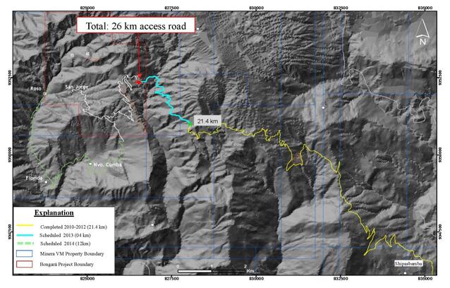
Source: Solitario, 2014
Figure 5-1: Photograph of the Florida Canyon Project Area
| 5.2 | Accessibility and Transportation to the Property |
Road access to the Bongará region is provided primarily by the Carretera Marginal paved highway connecting the port city of Chiclayo to Pedro Ruiz Gallo (inland). Travel time to Pedro Ruiz takes on average 6 hours by car. Pedro Ruiz is a regional commerce center with hotels, restaurants, communication and a population estimated to be 10,000. The immediate Project area is not populated but there are several small villages nearby.
| 42 |
The access routes to the town of Pedro Ruiz near the Florida Canyon Project area, as well as the distance and road conditions are summarized in Table 5-1.
Table 5-1: Distance and Travel Time to Florida Canyon Project from Lima, Peru
| Route | Distance (km) | Travel time (hours) | Access |
| Lima-Chiclayo | 800 | 1 hour 20 min | air |
| 10 hours | asphalt | ||
| Chiclayo-Pedro Ruiz Gallo | 300 | 6 hours | asphalt |
| Total | 10 hours | air | |
| 1 ½ days | ground |
Source: Solitario, 2014
| 5.3 | Climate and Length of Operating Season |
The climate at the Project is high altitude tropical jungle. The annual temperature at elevations between 1,000 masl and 2,000 masl averages around 25°C. Most precipitation occurs during the rainy season, between November and April. The annual rainfall average exceeds 1 m with up to 2 m in the cloud forest at higher elevations. Although exploration can continue year-round, surface exploration is more difficult during the rainy season when visibility hampers helicopter supported programs and muddy conditions hinder ground travel.
| 5.4 | Sufficiency of Surface Rights |
The Project concession package provides legal basis for entry, exploration and mining. However, agreements are required with local surface rights owners prior to surface disturbing activities. Through the exploration period conducted to date, Votorantim has signed bi-annual agreements for the use of Surface Lands. These agreements establish the commitments and counter-commitments to which both parties are bound (Company and community or private owner).
| 5.5 | Infrastructure Availability and Sources |
The Project area has little existing infrastructure with only an access road under construction and a number of primitive camps and drill pads (Figure 5-2 and Figure 5-3). Drilling has been accomplished using helicopter support from the village of Shipasbamba which lies 10 km to the southeast. The Project core shed and sample storage facility is located in Shipasbamba.
Proposed infrastructure presented as part of this PEA includes the following:
| · | Portal facilities (3) for underground mine access; |
| · | Mobile crushing plant at portals; |
| · | Water storage and supply piping; |
| · | Process plant; |
| · | Conveyor systems for ore and tailings; |
| · | Dry stack TSF; |
| · | Surface access roads; |
| · | Powerlines from offsite power supply; and |
| · | Mine camp, accommodations, water treatment facility. |
| 43 |
Source: Votorantim, 2013a
Figure 5-2: Project Access Road
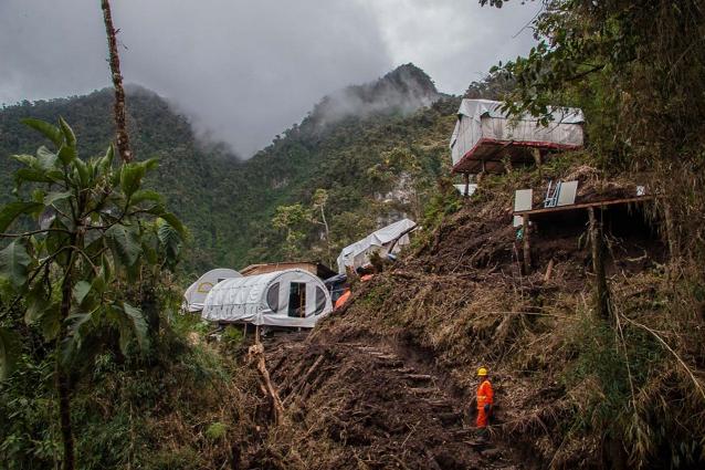
Source: Solitario, 2014
Figure 5-3: Photograph of Drilling Camp at Project Site
| 44 |
5.5.1 Proximity to Population Center
The Project has an office in Pedro Ruiz and a core shed and heliport located in the town of Shipasbamba nearer the deposit. No services are available in Shipasbamba. Drill sites, field camps and underground workings are located 10 km northwest of Shipasbamba. The small community of Florida is 1 to 2 km south of the drill camps on the foot trail from Tingo to the Project. Florida is a one to two hour walk from the largest field camp at El Roso. Road construction is planned to connect the drill camps and Florida.
Pedro Ruiz is the nearest town with commercial service including retail, hotels, restaurants and maintenance services. The nearest largest city with regular air service is Chiclayo, a coastal port city or Jaen, a small city approximately three hours by road. A paved air strip is available for private aircraft at Bagua Grande two hours from Pedro Ruiz on the Carretera Marginal road.
The small population near the Project is supported by subsistence farming. Saleable crops include coffee, rocoto pepper, yucca, fruit and vegetables. Cedar trees are also harvested and used in local construction.
5.5.2 Power
There is currently no substantive line power near the site. SRK considered a diesel-powered generator option for power supply. However, a third-party supplier, Energoret S.A.C, has a hydropower generation and transmission development project that will be located in close proximity to the mine. The Energoret system will generate 20 MW of power from a plant on a tributary to the Utcubamba River. Energoret indicates that half of the project, approximately 10 MW, has already been committed. The plant is designed to provide power to the city of Bagua Grande, west of their project, and to Pedro Ruiz to the east of Florida Canyon. Energoret indicates that it will invest in a transmission line to the Florida Canyon mine site and a substation on site.
5.5.3 Water
The operation will require water for use for processing, mining, dust suppression and potable consumption. The processing facility will utilize recycled water from the tailings facility and rainfall shed from the tailings for the majority of the processing needs. It is anticipated that there will be some ground water that will be encountered in the mine and captured in sumps and decantation basins for mine water needs.
Tesoro Creek, a small local drainage, has been used for domestic water supply by nearby residents. Clean water from this creek may be used for make-up process water, for fire suppression and for domestic requirements. It will be piped by gravity from the creek to a water storage tank. A small treatment plant will be utilized for potable water needs for town site and other support areas.
5.5.4 Mining Personnel
No trained mining personnel reside near the Project. Untrained labor is readily available from local communities where few employment opportunities exist. Peru is a mature mining country with a mobile workforce. Abundant trained labor is present in all categories of mining throughout Peru.
| 45 |
5.5.5 Potential Mine Infrastructure Areas
Potential sites for mine infrastructure, including a processing plant, tailings impoundment and waste rock storage are located east of the San Jorge deposit. A schematic diagram of planned infrastructure is shown in Figure 5-4. A detailed discussion of planned infrastructure for the Project is found in Section 18 of this report.
| 46 |
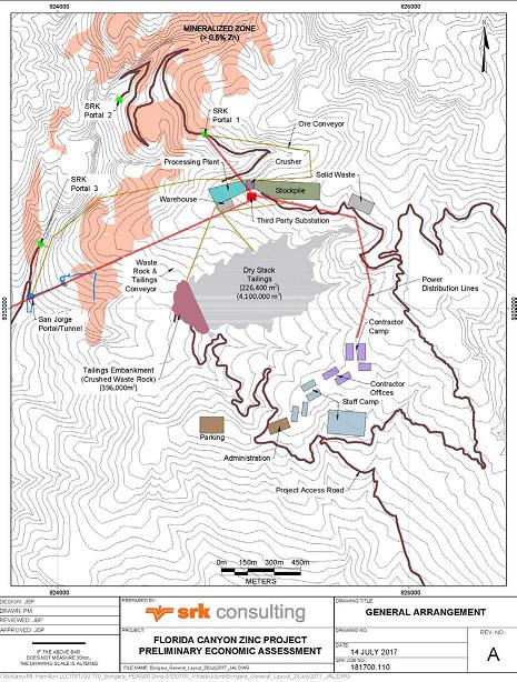
Source: SRK, 2017
Figure 5-4: Potential Mine Infrastructure Locations
| 47 |
| 6 | History |
| 6.1 | Prior Ownership and Ownership Changes |
Prior to the discovery of mineral occurrences by Solitario in 1994, no mineral prospecting had been done on the Property and no concessions had been historically recorded. In 1995 and later, Solitario staked the current mineral concessions in the Project area.
In 1996, Cominco Ltd. formed a joint venture partnership (JV) with Solitario. This agreement was terminated in 2000 and Solitario retained ownership of the property.
In 2006, and Solitario formed a JV with Votorantim for the exploration and possible development of the property.
| 6.2 | Previous Exploration and Development Results |
In 1993 through 1995, Solitario executed a program of pitting and drilling at the previously known Mina Grande and Mina Chica oxide zinc prospects located 18 km northeast of the Project area. Solitario subsequently identified the Crystal prospect nearby and other zinc occurrences in the general area. The Florida Canyon zinc deposit was located through follow-up of an anomaly generated during a regional program of stream sediments in 1994.
In 1997 to 1999, Cominco Ltd. completed various types of field work including geologic mapping, geophysical surveys, surface sampling, and diamond drilling. The scope of these programs is summarized below.
| · | Geologic mapping at 1:1,000 scale covering 352 ha in the Project area. Mapping was conducted within Florida Canyon and its tributaries aided by cut trails. Mapping has been validated by Votorantim. |
| · | Known mineralized outcrops in the Project area were cleared and sampled and a total of 347 rock chip channel samples were collected. This sampling consisted of channels with individual samples of thicknesses up to 2.0 m at non-regular spacing. |
| · | Sediment sampling of major drainages and streams was completed with consistent 500 m spacing along the drainages. |
| · | Soil samples were collected along topographic contour lines spaced vertically 50 m apart but with irregular lateral spacing. Part of this soil sampling followed the crests of hills, especially in the western part of Florida Canyon, mainly to identify mineralized linear structures. A total of 600 samples were collected. |
| · | Diamond drilling between 1997 and 2000 totaled 82 holes and 24,781 m. |
| · | An Induced Polarization (IP) geophysical survey in 3 lines covered 5.2 linear km. Two lines were located along the drainages A and B of the northern part of Florida Canyon with dipole- dipole spacing at 150 m, and a third line with dipole-dipole spacing a = 100 m along the southern sector of the Sam Fault target. Cominco also surveyed 6.5 km of radial lines from holes FC-41 and FC-47, drilled in 1999. |
| 6.3 | Historical Mineral Resource and Reserve Estimates |
The current Mineral Resource Statement for the Florida Canyon zinc-lead-silver deposit was prepared in June of 2014 pursuant to the requirements of NI 43-101. The statement is presented in Table 6-1.
| 48 |
Table 6-1: Mineral Resource Statement for the Florida Canyon Zn-Pb-Ag Deposit, Amazonas Department, Peru, SRK Consulting (U.S.), Inc., 05 June, 2014
|
Category |
Mass | Grade | Contained Metal (millions) | |||||||
| Zn | Pb | Ag | ZnEq | Zn | Pb | Ag | ZnEq | |||
| (Mt) | (%) | (%) | (g/t) | (%) | (Mlbs) | (Mlbs) | (Moz) | (Mt) | (Mlbs) | |
| Measured | 1.43 | 13.02 | 1.85 | 19.3 | 15.45 | 410.0 | 58.3 | 0.884 | 0.221 | 486.5 |
| Indicated | 1.35 | 12.51 | 1.71 | 17.1 | 14.74 | 372.6 | 50.9 | 0.744 | 0.199 | 438.8 |
| Measured + Indicated | 2.78 | 12.77 | 1.78 | 18.2 | 15.10 | 782.5 | 109.2 | 1.628 | 0.420 | 925.3 |
| Inferred | 9.07 | 10.87 | 1.21 | 12.2 | 12.44 | 2,173.0 | 241.5 | 3.554 | 1.130 | 2,487.6 |
Source: SRK, 2014
| · | Mineral Resources are not Mineral Reserves and do not have demonstrated economic viability. There is no certainty that all or any part of the Mineral Resources estimated will be converted into Mineral Reserves; |
| · | Mineral resources are reported to an NSR zinc-equivalent (ZnEq%) cut-off grade based on metal price assumptions*, metallurgical recovery assumptions**, mining costs, processing costs, general and administrative (G&A) costs, and NSR factors***. Mining costs, processing, G&A, and transportation costs total US$51.30/t. |
| · | *Metal price assumptions considered for the calculation of metal equivalent grades are: Zinc (US$/lb 0.95), Lead (US$/lb 0.95) and Silver (US$/oz 20.00), |
· **Cut-off grade calculations assume variable metallurgical recoveries as a function of grade and relative metal distribution. Average metallurgical recoveries for sulfide and oxide respectively are: Zinc (93.1%, 73%), Lead (84.8, 0%) and Silver (55.6%, 0%)
| · | *** NSR factors for calculating cut-off grades were: ZnEq% = Zn% * 1 + Pb% * 0.74 + Ag g/t * 0.02 |
| · | Resulting cut-off grades used in this resource statement were 4.1% ZnEq for sulfide, 5.0% ZnEq for oxide, and 4.5% ZnEq for mixed material types. |
| · | Zinc equivalency for reporting in situ resources was calculated using: |
· ZnEq (%) = Zn (%) + 1.0 * PB (%) + 0.03 * Ag (g/t)
| · | Density was calculated based on material types and metal grades. The average density in the mineralized zone was 2.91 g/cm3 as a function of the zinc and lead sulfide mineral content. |
| · | Mineral Resources as reported are undiluted. |
| · | Mineral resource tonnage and contained metal have been rounded to reflect the precision of the estimate, and numbers may not add due to rounding. |
o There are no Mineral Reserves previously developed for the deposit.
| 6.4 | Historical Production |
There has not been any commercial mining in the Project area. The only underground excavation has been 700 m of underground drifting by Votorantim to provide drill platforms at the San Jorge area.
A subsidiary of Hochschild Mining PLC tested open pit mining for a short time at the Mina Grande deposit off of the claims held by Votorantim and Solitario near the village of Yambrasbamba, 18 km northeast of Florida Canyon, where Solitario had previously defined an oxidized zinc resource by pitting.
| 49 |
| 7 | Geological Setting and Mineralization |
Information presented herein is derived from material provided by Votorantim and Solitario, including Cominco reports, and was verified and augmented by SRK during a site visit in May 2014.
| 7.1 | Regional Geology |
The Project is located within an extensive belt of Mesozoic carbonate rocks belonging to the Upper Triassic to Lower Jurassic Pucará Group and equivalents. This belt extends through the central and eastern extent of the Peruvian Andes for nearly 1000 km and is the host for many polymetallic and base metal vein and replacement deposits in the Peruvian Mineral Belt. Among these is the San Vicente Mississippi Valley Type (MVT) zinc-lead deposit that has many similarities to the Florida Canyon deposit and other MVT occurrences in the Project area. A regional geologic map is shown in Figure 7-1.
| 50 |
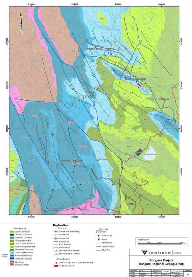
Source: Solitario, 2014
Figure 7-1: Regional Geologic Map
| 51 |
| 7.2 | Local Geology |
7.2.1 Lithology and Stratigraphy
A schematic stratigraphic column developed by Cominco and refined by Votorantim shows the major geologic rock units in the Project area (Figure 7-2). The basement rocks are the Pre-Cambrian Marañón Complex consisting of gneisses, mica-schists, phyllites and quartzites. These are overlain by an angular unconformity with the overlying Permo -Triassic Mitu Group composed of a sequence of redbeds consisting of polymictic conglomerates interspersed with beds of fine-grained sandstones.
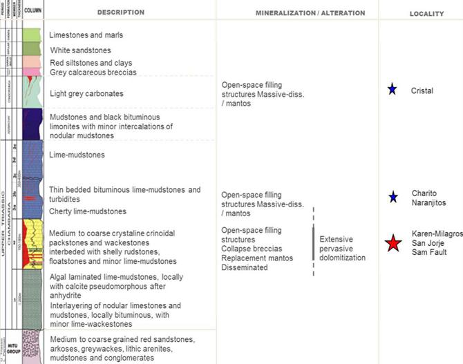
Source: Votorantim, 2013b, translated by Solitario
Figure 7-2: Project Area Stratigraphic Column
Overlying the Mitu Group is the Pucará Group of Triassic - lower Jurassic age, which hosts the zinc- lead-silver mineralization of the Florida Canyon Project. The Pucará Group is divided into the Chambara Formation at the base, the Aramachay Formation in the middle and the Condorsinga Formation on top.
| 52 |
The Chambara formation has an approximate thickness between 650 m and 750 m in the project area, and consists of crinoidal packstone, wackstones and rudstones. It is divided into three members in the Florida Canyon vicinity; from bottom to top, they are Chambara 1, Chambara 2 and Chambara 3. The bulk of known zinc mineralization is hosted in Chambara 2. The stratigraphy between the distinctive Coquina (CM) and Intact Bivalve (IBM) paleontological marker horizons in Chambara 2 define a sequence of permeable higher energy facies within the Chambara 2 that control much of the especially strong dolomitization within the sequence.
The Aramachay formation lies concordantly on the Chambara with a variable thickness between 150 m and 250 m, consisting of a monotonous sequence of black and limonitic lutites and bitumen with thin interbedded nodular limestones. The Condorsinga Formation concordantly lies above, with restricted outcrop distribution due to erosion. It consists of calcareous gray mudstones with thicknesses varying between 150 m and 300 m.
The Corontochaca Formation of Upper Jurassic age lies unconformably on the Pucará Group. It outcrops in erosional remnants and is locally more than 300 m thick consisting of a package of monotonous oligomictic and polymictic fluvial calcareous sediments and colluvial limestone breccias with local fragments of Paleozoic or Precambrian fragments.
The Goyllarisquizga Formation occurs in angular unconformity over the Corontochaca and Pucará Group and is present mainly in the eastern and western sections of the Project area. It consists of poorly sorted yellowish to white sandstone deposited in coastal marine to fluvial-deltaic environments. It also contains some thin, lenticular intercalations of siltstones and mudstones whitish to reddish. The thickness ranges from 300 to 400 m.
7.2.2 Structure
The following discussion of structural geology in the Project area is adapted in part from an internal report by Cominco (2000).
The structure at Florida Canyon is dominated by a N50º-60ºW trending domal anticline (or doubly- plunging anticline) as defined from the base of Chambará 2 structural contour map in Figure 7-2. This domal anticline is cut on the west by the Sam Fault and to the east by the Tesoro-Florida Fault. The Sam Fault, which has been defined by drilling, has a north-south to northeast trend and a steep 80 to 85º westerly dip. The Sam Fault has an apparent scissor dip-slip displacement of >120 m in the north and <50 m in the south. To the south its trace is uncertain and complicated by northwest and possibly east-west structures. This appears to have been a long-lived structure, with its last strike-slip displacement being dextral. A facies change in the Chambará 2 from high energy to the east of the fault to low energy to the west many be due to original depositional features during growth fault formation that has important exploration implications.
At Florida Canyon there are also well defined northwest and northeast fracture systems, which appear to have important controls on the location of mineralization. Mineralized structures occur in conjugate fractures, with N10º-50ºE trends present at a number of mineralized surface outcrops while trends of N50º-80ºW are identified at other showings. Mineralization of mantos within the Karen-Milagros area appears to be preferentially controlled by northeast feeder structures.
The Tesoro-Florida Fault defining the eastern limits of most drilling to date is a N15º-30ºW trending structure, part of a regional lineament, and defined by an escarpment. It is interpreted to have a steep dip, with its sense of motion not having been defined, but with the east block being structurally lower than the west block, which results in significantly deeper drilling on the east fault block to reach the Chambará 2 stratigraphy. Because most of the work has concentrated further west on the San Jorge, Karen Milagros and Sam Fault areas there is little information on the Tesoro-Florida Fault, but it likely has similarly complex splays as the Sam Fault and may be, like the Sam fault, a controlling feeder for untested mineral potential in the eastern area.
| 53 |
At both the Karen-Milagros and San Jorge areas, feeder structures have an important control on the mineralized mantos but also represent a significant portion of the resource as steeply dipping structural fillings and replacement. The displacement along these structures is not large although the exact throw is often difficult to ascertain due to the strong alteration and later mineralization. The interpretation of displacement is further obscured by likely subtle variation in thickness and lithology of local stratigraphic units on either side of structures due to growth faulting.
Pre-mineral karsting also played a role in controlling mineralization along with simple structural filling and passive replacement adjacent to conduits. Replacement of karst fragments and cave sediments are commonly observed in larger structurally controlled mineralized bodies. The configuration of mineralized structures as they control and merge with manto replacements often take the form of Christmas–tree breakthrough structures and will likely be shown to represent a larger proportion of the resource as more horizontally oriented drilling from underground workings supplants the dominantly high angle surface drilling performed to date.
Post mineral structure and karsting overprints earlier structural trends and controls in part oxidized remobilized mineralization.
7.2.3 Alteration
The alteration and solution overprints in the Florida Canyon deposit include dolomitization, pseudobrecciation and karstification, mainly affecting the limestones of Chambara 2 and locally Chambara 1 and 3. Dolomitization and karstification occurred in multiple events spatially overlapping the structural corridors Sam, San Jorge and Karen-Milagros. Dolomitization was an important control on the movement of mineralizing fluids and has been studied and logged in detail throughout all of the drilling campaigns. It is also modeled in this study as a limiting constraint on mineralization.
The alteration halo is open in all directions and is especially pervasive in the stratigraphic interval lying between the paleontological marker horizons CM (Coquina Marker) and IBM (Intact Bivalve Marker) of the Chambara 2 formation. The alteration halo is composed mostly of medium and coarse-grained crystalline dolomite replacing calcareous packstone, rudstones, floatstones and wackestones. Mostly the dolomitic rudstones, and locally the packstones, transform laterally when in proximity of faults and major fractures (Sam, San Jorge and Karen-Milagros) to mineralized pseudobreccias and karst structures.
7.2.4 Mineralization
The zinc-lead-silver mineralization of the Florida Canyon deposit occurs as sulfides hosted in dolomitized zones of the Chambara 2 Formation. Dolomite paragenesis and later sulfide mineralization are controlled by a combination of porosity, permeability and structural preparation. Metals occur in sphalerite and lesser galena, which contains silver. Minor mineralization is hosted in limestones, but the bulk of sphalerite and galena is hosted in dolomite.
In a number of core samples, the mineralization has very sharp contacts along the dolomitization boundary. Characteristic mineralization textures include massive and disseminated mantos mineralization in dissolution breccias, collapse breccias and pseudobreccias. The different breccias and vein types are structurally controlled by faults of north-south and northeast-southwest direction.
| 54 |
The mineralization is characterized by the presence of sphalerite, galena and locally pyrite. Sulfide replacements occur in dolomitized limestone of variable grain sized and in solution breccias with white dolospar and lesser amounts of late generation calcite. Pyrite content is generally low, with percentages averaging less than 2% by volume. Sphalerite in mineralized sections has variable grain size from 0.1 to greater than 5 mm, with colors ranging from dark brown through reddish brown to light brown. It occurs as individual crystals or in massive form, sometimes displaying colloform textures with bands of slightly differing color zoning, indicators of polyphase hydrothermal deposition.
Early fine-grained sphalerite has evidence of later deformation and reactions to secondary mineralizing fluids. A second phase of more massive sphalerite mineralization is observed within the core of the deposit. These crystals are coarse-grained, regular, euhedral and show very little evidence of any post-depositional deformation. The sphalerite is contemporaneous with fine to coarse grained galena and is often overprinted with a later stage coarse-grained, euhedral galena.
The presence of zinc oxides, locally to considerable depths, is due to syngenetic oxidation, with later contributions of basin-derived connate water and movement of rainwater through fractures that leached the limestones and formed significant karst cavities.
| 7.3 | Property Geology |
The areas of current exploration interest are the Karen/Milagros, San Jorge and Sam Fault deposits. These mineralized zones are hosted in the dolomitized Chambará 2 sub-unit of the Pucará Group carbonates, bracketed by the Coquina and Intact Bivalve Marker beds. Geologic mapping and modeling includes refining the extents of Chambará 2, and further defining the steeply dipping feeder structures to predict additional zinc-lead-silver mineralization. The outcrop geology of the deposit area is shown in Figure 7-3, with emphasis on the Chambará Formation.
| 55 |
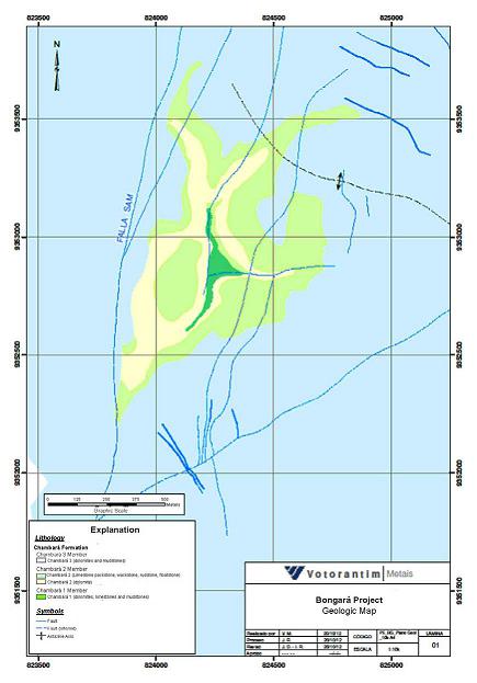
Source: Solitario, 2014
Figure 7-3: Florida Canyon Project Geologic Map
| 56 |
| 7.4 | Significant Mineralized Zones |
Local and regional geologic mapping, geologic drillhole logs, and the dome-shaped geometry of the deposit suggest the mineralization is hosted in a broad anticline structure. Florida Canyon is the collective name of the deposits in the Project area in Florida Canyon, and includes the Karen-Milagros, San Jorge, Sam Fault zones and similar mineralized strata between these areas.
Modeled manto zones are between 1 m and 9 m thick and occur over an area of about 1 km x 3 km and are open in all directions. Unmineralized gaps exist within the mineralized manto zones, as is typical for hydrothermal replacement deposits. Irregular steeply dipping replacement bodies also occur, frequently at the intersection of vein-like feeder structures and in karst-controlled mineralization.
Mineralization outcrops locally in a number of areas, and have been drilled at depths of up to about 450 m below ground surface. Figure 7-4 is a west-facing cross section of the geologic model in the mineralized zone. Zinc mineralization occurs as massive sphalerite (ZnS), and is locally oxidized to smithsonite (ZnCO3) and hemimorphite (Zn4Si2O7 (OH)2). Lead occurs in galena (PbS), cerussite (PbCO3) and anglesite (PbSO4).
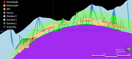
Source: Votorantim, 2013b
Figure 7-4: Cross Section of the Project Geologic Model
| 57 |
| 8 | Deposit Type |
MVT deposits are hosted in carbonate rocks, and show cavity-filling or replacement-style mineralization. The characteristic minerals are sphalerite, galena, fluorite, and barite. The host rock may be silicified, and common alteration minerals include dolomite, calcite, jasperoid and silica. MVT deposits are typically spatially extensive, but limited by the permeability of the host rock units. This control makes them appear stratabound. Chemical and structural preparation are the main controls on permeability, and therefore, the extent of fluid migration and metal precipitation (Guilbert and Park, 1986).
| 8.1 | Mineral Deposit |
An area of 20 km x 100 km extending from Mina Grande to north to 80 km south of the Florida Canyon deposit has become the focus of what is an emerging Mississippi-Valley Type (MVT) zinc and lead province, with many surface occurrences and stream sediment anomalies distributed throughout the Pucará Group. The main host rock of zinc and lead occurrences in the mineral district and Project area is dolomitized limestone, which may show karst or collapse breccia textures.
| 8.2 | Geological Model |
The current genetic model for Florida Canyon consists of mineralization being classified as syn-to post tectonic. Specifically, upwelling mineralizing fluids entered the Chambara Formation and precipitated in porous and reactive dolomites with interaction of sulfide and organic ions (H2S and CH4) resulting from reaction with overlying evaporitic and bituminous sequences, all channeled by axial planar faults. The schematic mineralization model is presented in Figure 8-1.
| 58 |
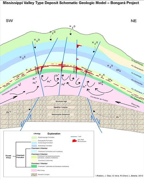
Source: Votorantim, 2014a
Figure 8-1: Mississippi Valley-Type Deposit Schematic Model
| 59 |
| 9 | Exploration |
| 9.1 | Relevant Exploration Work |
The Florida Canyon Project has identified and delineated mineral resources in the San Jorge, Sam and Karen-Milagros areas. The results and methodology are described below.
In earlier years Cominco and then Votorantim executed detailed surface mapping programs, mineralized outcrop clearing and mapping and sampling of the areas near the reported resource. Stream sediment and soil samples were collected and analyzed as described in Section 6.2. An extensive regional reconnaissance exploration program was also conducted over a large area throughout the Mesozoic carbonate belt to the north and south of the Property. Geochemical samples were collected of stream sediments, soils and rocks.
During development of the San Jorge adit, Votorantim completed geologic mapping and chip sampling of the underground workings. Results were applied to the Project geologic model in support of resource estimation and continued exploration drillhole planning.
Future exploration work will focus on infill drilling between the Karen-Milagros, San Jorge and Sam areas. Mineralization is open to the north and south and remains largely untested to the east of the Tesoro Fault and west of the Sam Fault where greater target depths have lowered the near-term drilling priority. As discussed in Section 9.4 prospective targets for grass roots exploration exist further north on the Project Property
| 9.2 | Surveys and Investigations |
Solitario, Votorantim and Cominco have not completed any additional surveys or other investigations outside of drilling, mapping and sampling surface and underground workings as described.
| 9.3 | Sampling Methods and Sample Quality |
Sampling of drill core is described in detail in Section 11. The regional stream sediment program collected sediments that were screened to -80 mesh, ashed and analyzed for a multielment suite by ICP. Soil samples collected were composites of B horizon soils and C horizon when accessible.
Rock sample methodology varied according to location. Grab samples were taken where outcrops were found that showed evidence of dolomitization of carbonate beds. Mineralized outcrops were cleared manually with machetes and shovels and systematically chip channeled. Channels were oriented perpendicular to bedding to most accurately represent stratigraphic thickness. Channel samples were limited to 2 m in length by Cominco and 1 m by Votorantim. Most of the chip channel sampling of higher grade mineralization has been conducted in the Karen Milagros zone and other areas in the central part of the Property where outcrops of mineralization are most common, as illustrated in Figure 9-1.
| 9.4 | Significant Results and Interpretation |
Exploration strategy for MVT deposits at the Florida Canyon project has been strongly influenced by the interpreted favorability of specific units of the stratigraphy of the region. Numerous occurrences of alteration and mineralization occur throughout the Pucara Group but economic deposits have only been thus far located within the Triassic Chambara formation (Stratigraphic Section, Figure 7.1).
| 60 |
More specifically the middle member of the Chambara Formation (Chambara 2) has been found to host the most persistent and highest grade manto deposits due to its higher permeability and susceptibility to altering and mineralizing fluids. Synsedimentary structures, formed during or slightly after sedimentation, controlled the flow of basinal brines that dolomitized and subsequently mineralized the carbonates. The mineral rich fluids migrated from these “feeders” laterally into the stratigraphic column to form mantos.
Economic resources have been delineated in both the stratigraphically controlled mantos as well as the feeders, such as the San Jorge and Sam mineralized bodies. The higher angle structures have also been subject to karst formation that further enhanced fluid flow and are themselves often well mineralized with higher grade wider mineralization e.g. San Jorge.
Particularly prospective locations to explore for these high grade, high tonnage deposits exist along the northeast trending lineaments (drainages) immediately north and south of Karen Milagros where outcropping massive mineralization may be expressions of breakthrough structures. These locations have not been adequately tested to date due to the difficult access for helicopter supported drilling. The completion of road access will facilitate testing of these targets.
| 61 |
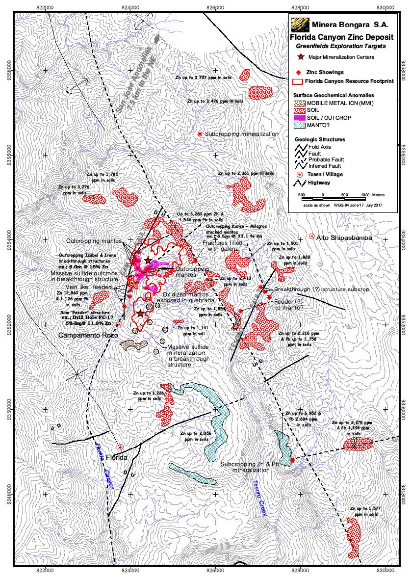
Figure 9-1: Florida Canyon Area Prospect and Geochemistry Map
| 62 |
These steeply dipping bodies occur over stratigraphic intervals that extend upwards into the Chambara 3, Aramachay and Condorsinga formations. The depth extent of mineralization in the feeders is currently unknown. These conduits enabled metal rich fluids to enrich the overlying stratigraphy and provide potentially important evidence for exploration.
Geochemical prospecting is very effective in locating the leakage halos in overlying stratigraphy around these structures. Initially stream sediments were used to identify geochemically enriched drainages and were followed up with prospecting and soil surveys to pinpoint mineralized centers. Although no detailed mapping has been done over much of the property, geologists made observations of the stratigraphic location within areas of high geochemical response.
Figure 9-2 shows the results of the regional geochemistry program. The area in the immediate vicinity of the Florida Canyon resource exhibits very high base metal content in stream sediment, soils and rocks. Only a small area of Chambara 2 crops out in this area as shown in orange color on the geologic map of the Florida/Tesoro vicinity (Figure 9-3). Outcropping high grade mineralization in this window of Chambara led to the initial discovery of the known Florida Canyon deposits.
Nearby, there are significant soil anomalies in higher stratigraphy that warrant future exploration drilling. These anomalies occur in undrilled areas within the horst that hosts the current resources as well as to the west of the Sam Fault and East of the Tesoro Fault.
Further to the north two very large and strong soil anomalies have been defined by the regional geochemical sampling program (Figure 9-2). The San Jose soil anomaly is of similar size and grade to that at Florida Cayon. It is, as yet, untested with drilling. Based on the clear relationship between surface geochemistry and subsurface mineralization at Florida Canyon, drilling is warranted in the San Jose and Naranjitos areas.
| 63 |
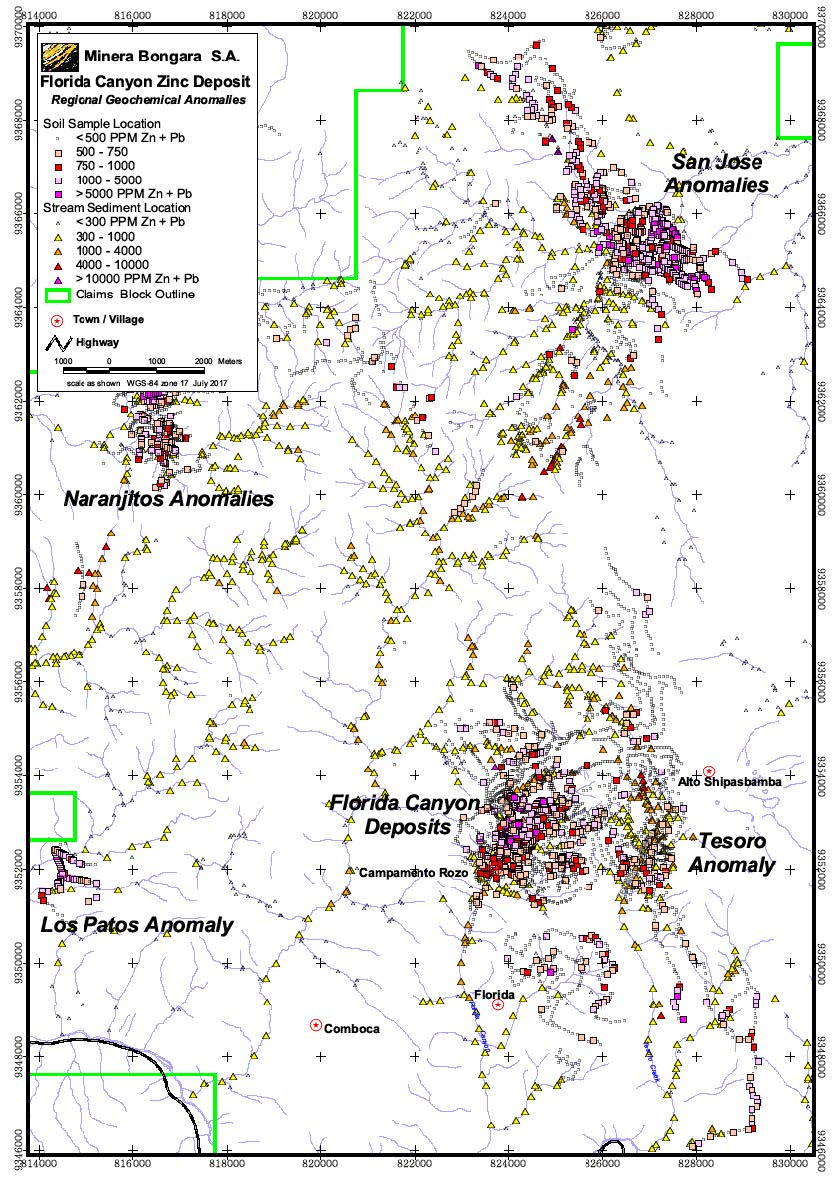
Figure 9-2: Regional Geochemical Results
| 64 |
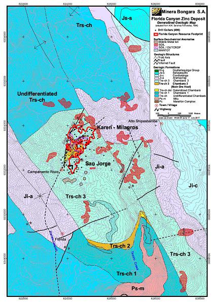
Figure 9-3: Florida Canyon Area Simplified Geology, Resource and Drillhole Map
| 65 |
| 10 | Drilling |
The database used for modeling and estimation of mineral resources has not been augmented since August 15, 2013 and includes 486 diamond drillholes, with a total of 117,280.25 m drilled length. There has been no new drilling on the project since the 2014 Technical Report (SRK, 2014b).
| 10.1 | Type and Extent |
All drillholes completed in the Project area are HQ-diameter core (63.5 mm). If poor ground conditions necessitated, the core diameter was reduced to NQ (47.6 mm). Cominco completed a total of 82 drillholes from the current ground surface in the Karen-Milagros and Sam deposit areas, and the San Jorge structural corridor. Votorantim completed 404 drillholes between 2006 and 2013, from surface or from the San Jorge Adit. The Votorantim drilling is distributed throughout the Project area. All holes mentioned above are included in the geologic modeling and resource estimation database, and shown in Figure 10-1.
The combined Cominco and Votorantim drilling for the project totals 117,260 m. Figure 10-2 shows drilled length by program, including 4,047 m of oriented core geotechnical drilling in 13 drillholes.
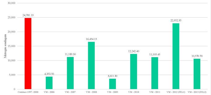
Source: Votorantim, 2013b
Figure 10-1: Project Drilling History
| 66 |
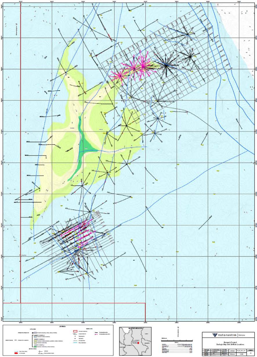
Source: Solitario, 2014
Figure 10-2: Geologic Map with Drillhole Locations
| 67 |
| 10.2 | Procedures |
All drilling contracted by Votorantim was completed with triple-tube HQ tooling and followed industry standard procedures to ensure sample quality. Surface drilling was executed with a helicopter- supported LD-250 diamond core rig operated by Bradley Bros. Limited. Sermin completed the underground development and also completed drilling from the San Jorge adit with a LM-70 electric diamond core rig.
Drilling was performed on two 12-hour shifts with full 24-hour geological supervision by a Votorantim geologist. The rig geologist role included:
| · | Coordination and communication between the drilling contractor and Votorantim; |
| · | Monitoring drilling procedures and inspecting the core extraction for sample quality; |
| · | Boxing the core; |
| · | Measuring and recording core recovery and Rock Quality Designation (RQD); and |
| · | Completing a preliminary geological log. |
Downhole surveys were completed with a Reflex EZ-Shot survey tool by the drillers at varying spacing, as summarized in Table 10-1. The survey records are stored digitally at the core facility and SRK reviewed them during the 2014 site visit. Drillhole collar locations were surveyed by Votorantim with a GPS- based instrument.
Table 10-1: Downhole Survey Data Point Spacing
| Drilling Program (Year) |
Survey Spacing (m) |
| 2010 | 100 |
| 2011 | 50 |
| 2012 to 2013 | 20 |
Source: SRK, 2014
Votorantim completed 13 oriented geotechnical drillholes, totaling 4,046.70 m. In these holes, the recovery was excellent (90% to 100%) with RQD results greater than 75%.
From the drill site, filled core boxes were transported in batches of 14 via helicopter to the drill core logging facility in Shipasbamba. These were photographed and fully logged by Votorantim geologists in natural light. During the 2012 to 2013 program, many of the core photographs were taken after the core had been cut for sampling, due to the large quantity of core produced.
| 10.3 | Interpretation and Relevant Results |
The geologic logging and analytical data were added to the Project database after validation and applied to modeling and resource estimation. Due to the large number of drillholes in the database, and because the modeling and resource estimation are discussed in detail, in Section 14 (Mineral Resources), the drilling results by interval are not presented here. The true thickness of the mineralized intercepts is about 80% of the drilled length, and varies with the orientation of the drillhole.
Votorantim’s documentation of drilling procedures and SRK’s observation of the program indicate that there is little or negligible sampling bias introduced during drilling.
| 68 |
SRK considers the drilling procedures to be appropriate for the geology, conducted according to industry best practice and standards, and the relevant results are sufficient for use in resource estimation.
| 69 |
| 11 | Sample Preparation, Analysis and Security |
| 11.1 | Sampling Methods |
Sampling procedures for core drilled on behalf of Cominco are not well-documented. Cominco included assay quality control samples in the analytical programs, but the results were not available to review. The resource classification from these samples is limited because the location and analytical data was not obtained according to current industry standard protocol.
Most of the information in this section pertains to the sampling completed by Votorantim. Available information about sampling completed by Cominco is included if available, and is specified as such. About 20% of the holes in the current drillhole database were drilled by Cominco.
11.1.1 Sampling for Geochemical Analysis
After photographing the core and completing geotechnical and geologic logging, a geologist marked the core for sample intervals that averaged 100 cm long. Samples had a minimum length of 30 cm and a maximum of 150 cm, but were defined so that 100 cm samples were maintained as much as possible. Cut lines parallel to the core axis were drawn by the logging geologist, to ensure nearly symmetrical halves and minimal sampling bias relative to any visible mineralization. The core was cut on a rock saw with a 40 cm blade, under supervision of a Project geologist. After the core was cut, both halves were replaced in the core box.
Samples were always taken from the left side of the saw-cut core, double bagged and marked with sample numbers in two places. These were transported in larger bags containing seven samples each by Mobiltours freight company to the ALS Minerals laboratory in Trujillo or Lima, operated by ALS Minerals. Prior to 2012, analysis was completed in Trujillo. Since then, it has been done in Lima.
Cominco also split the core samples and sampled half for geochemical analysis. Sample breaks were determined by geologic criteria. Cominco core samples were analyzed by Acme Labs, in Lima, Peru.
11.1.2 Sampling for Density Measurement
Specific gravity (SG) measurements were completed on site by Votorantim on every sample from the 2013 drilling program. For previous drilling programs, SG measurements were completed on all mineralized intervals. Three SG measurement methods were used:
| · | Volume displacement; |
| · | Hydrostatic; and |
| · | A mesh method for broken material. |
These techniques were designed and implemented by Inspectorate Services Peru SAC. Votorantim has also performed some density measurements on older Cominco core.
| 11.2 | Security Measures |
During the SRK site visit, the observed sample storage was secure, and provided adequate protection from rainfall. Sample security and chain of custody was maintained while the samples were transported from the core shed in Shipasbamba to Lima. Assay certificates are retained in the Votorantim office in Lima.
| 70 |
Analytical data is loaded directly from the laboratory results files to the drillhole database, to minimize the risk of accidental or intentional edits.
| 11.3 | Sample Preparation for Analysis |
ALS Minerals (ALS) in Trujillo or Lima, Peru, completed sample preparation and analysis for all Votorantim core samples. ALS is an independent, global analytical company recognized for quality, and is used by many exploration and mining companies for geochemical analysis. Current certifications and credentials include ISO 17025:2005 Accredited Methods & ISO 9001:2008 Registration in Peru, Brazil, Chile and Argentina (ALS Minerals, 2014a).
Upon delivery at the lab, bar coded sample identification labels were scanned and the samples were registered to the Laboratory Information Management System (LIMS). Samples were weighed, and then air-dried in ambient conditions. Excessively wet samples were dried in an oven at a maximum 120°C. The sample preparation and analysis procedures used are summarized in Table 11-1. Specific analytical procedures and method detection limits for elements in the suite are reported in Table 11-2.
After analysis is complete, the remaining coarse reject and pulp samples are returned to the Florida Canyon core shed for storage.
Cominco analyzed samples with visible zinc or lead mineralization by atomic absorption spectrophotometry. All samples containing greater than 10,000 ppm zinc + lead were then analyzed by wet chemistry and the latter results were recorded in the data base.
Table 11-1: Analytical Codes and Methods
| Procedure Code | Description |
| Sample Prep | |
| CRU-31 | Crush to 70% less than 2 mm. |
| SPL-21 | Riffle split off 1kg and retain the coarse reject. |
| PUL-32 | Pulverize split to better than 85% passing 75 microns. |
| Multi-Element Methods | |
| ME-ICP61, -a | Multi-element Inductively-Coupled Plasma method with Atomic Emission Spectroscopy analysis. Includes 4-acid, "near-total" digestion of 0.5 g sample. |
| (+)-AA62 | HF, HNO3, HClO4 digestion, HCl leach and Atomic Absorption Spectroscopy analysis. |
| (+)-VOL70 | Volumetric titration for very high grade samples. |
| XRF10 | X-Ray fluorescence on fused pellet, 5 g sample. |
| Element-Specific Methods | |
| Au-AA23 | Gold by fire assay and Atomic Absorption Spectrometry, 30 g sample. |
| Au-AA25 | Ore-grade gold by fire assay and Atomic Absorption Spectrometry, 30 g sample. |
| Au-GRA21 | Gold by fire assay and gravimetric finish, 30 g sample. |
| Hg-CV41 | Trace level mercury by aqua regia and cold vapor/AAS. |
| Hg-ICP42 | High grade mercury by aqua regia and ICP-AES. |
| In-MS61 | Multi-element Inductively-Coupled Plasma method with Mass Spectrometry detection. Includes 4-acid, "near-total" digestion of 0.5 g sample. |
| S-IR08 | Total sulfur by Leco furnace. |
Source: ALS Minerals, 2014b, compiled by SRK, 2014
| 71 |
SRK Consulting (U.S.), Inc.
NI 43-101 Technical Report, Preliminary Economic Assessment – Florida Canyon Zinc Project Page 72
Table 11-2: Analyzed Elements and Method Detection Limits
| Element | Symbol | Method | Unit | Lower MDL | Upper MDL | Overlimit Method | Unit | Lower MDL | Upper MDL | Overlimit Method | Unit | Lower MDL | Upper MDL |
| Silver | Ag | ME-ICP61 | ppm | 0.5 | 100 | Ag-AA62 | ppm | 1 | 1,500 | ||||
| Aluminum | Al | ME-ICP61 | % | 0.01 | 50 | ||||||||
| Arsenic | As | ME-ICP61 | ppm | 5 | 10,000 | ||||||||
| Barium | Ba | ME-ICP61 | ppm | 10 | 10,000 | ME-ICP61a | ppm | 50 | 50,000 | XRF10 | % | 0.01 | 50 |
| Beryllium | Be | ME-ICP61 | ppm | 0.5 | 1,000 | ||||||||
| Bismuth | Bi | ME-ICP61 | ppm | 2 | 10,000 | ||||||||
| Calcium | Ca | ME-ICP61 | % | 0.01 | 50 | ||||||||
| Cadmium | Cd | ME-ICP61 | ppm | 0.5 | 1,000 | Cd-AA62 | % | 0.0005 | 10 | ||||
| Cobalt | Co | ME-ICP61 | ppm | 1 | 10,000 | ||||||||
| Chromium | Cr | ME-ICP61 | ppm | 1 | 10,000 | ||||||||
| Copper | Cu | ME-ICP61 | ppm | 1 | 10,000 | ||||||||
| Iron | Fe | ME-ICP61 | % | 0.01 | 50 | ||||||||
| Gallium | Ga | ME-ICP61 | ppm | 10 | 10,000 | ||||||||
| Potassium | K | ME-ICP61 | % | 0.01 | 10 | ||||||||
| Lanthanum | La | ME-ICP61 | ppm | 10 | 10,000 | ||||||||
| Magnesium | Mg | ME-ICP61 | % | 0.01 | 50 | ||||||||
| Manganese | Mn | ME-ICP61 | ppm | 5 | 100,000 | ||||||||
| Molybdenum | Mo | ME-ICP61 | ppm | 1 | 10,000 | ||||||||
| Sodium | Na | ME-ICP61 | % | 0.01 | 10 | ||||||||
| Nickel | Ni | ME-ICP61 | ppm | 1 | 10,000 | ||||||||
| Phosphate | P | ME-ICP61 | ppm | 10 | 10,000 | ||||||||
| Lead | Pb | ME-ICP61 | ppm | 2 | 10,000 | Pb-AA62 | % | 0.001 | 20 | Pb-VOL70 | % | 0.01 | 100 |
| Sulfur | S | ME-ICP61 | % | 0.01 | 10 | S-IR08 | % | 0.01 | 50 | ||||
| Antimony | Sb | ME-ICP61 | ppm | 5 | 10,000 | ||||||||
| Scandium | Sc | ME-ICP61 | ppm | 1 | 10,000 | ||||||||
| Strontium | Sr | ME-ICP61 | ppm | 1 | 10,000 | ||||||||
| Thorium | Th | ME-ICP61 | ppm | 20 | 10,000 | ||||||||
| Titanium | Ti | ME-ICP61 | % | 0.01 | 10 | ||||||||
| Thallium | Tl | ME-ICP61 | ppm | 10 | 10,000 | ||||||||
| Uranium | U | ME-ICP61 | ppm | 10 | 10,000 | ||||||||
| Vanadium | V | ME-ICP61 | ppm | 1 | 10,000 | ||||||||
| Tungsten | W | ME-ICP61 | ppm | 10 | 10,000 | ||||||||
| Zinc | Zn | ME-ICP61 | ppm | 2 | 10,000 | Pb-AA62 | % | 0.001 | 30 | Zn-VOL70 | % | 0.01 | 100 |
| Gold | Au | Au-AA23 | ppm | 0.005 | 10 | Au-AA25 | ppm | 0.01 | 100 | Au-GRA21 | ppm | 0.05 | 1,000 |
| Indium | In | In-MS61 | ppm | 0.005 | 500 | ||||||||
| Mercury | Hg | Hg-CV41 | ppm | 0.01 | 100 | Hg-ICP42 | % | 0.1 | 10 |
Source: Votorantim (2014b), translated by SRK
| 72 |
| 11.4 | QA/QC Procedures |
Votorantim’s Technical Report (Votorantim, 2014b) includes assay quality assurance/ quality control (QA/QC) results available through June 15, 2013. Sample dates in the QA/QC data files are between 2011 and 2013, and no information for prior samples was available. For the 2011 to 2013 drilling programs, assay QC samples were 10.9% of the total samples analyzed. Some programs included duplicate core or coarse reject samples, and/or duplicate analysis of fine pulp samples. Votorantim compiled and analyzed the results from 2011 to 2013 drilling programs, which SRK has reviewed and summarized below. Assay QC results from drilling programs prior to 2011 were not available to include in this report.
11.4.1 Standards
Summaries of the Standard Reference Material (SRM) certified values and analytical results for lead and zinc are shown in Table 11-3 and Table 11-4, respectively. The certified Standard Reference Material, ST800044B, was included in the core sample suite, and is highlighted with bold text in the tables. Other, lower-grade reference materials made from Florida Canyon core were also included.
Table 11-3: Summary of SRM Statistics for Lead
| Pb SRM | Mean (ppm) |
Standard Deviation (ppm) |
Samples | Outliers | Percent Outliers | Bias |
| STD_RK1 | 13.4 | 2.35 | 127 | 1 | 1% | -4.3% |
| STD_RK2 | 439.18 | 17.26 | 154 | 2 | 1% | 2.6% |
| STD_RK3 | 3149.47 | 113.00 | 134 | 0 | 0% | -2.9% |
| ST800044B | 18100 | 500 | 80 | 0 | 0% | 0.3% |
Source: Votorantim (2014b), formatted and translated by SRK
Table 11-4: Summary of SRM Statistics for Zinc
| Zn SRM | Mean (ppm) |
Standard Deviation (ppm) |
Samples | Outliers | Percent Outliers | Bias |
| STD_RK1 | 22.93 | 4.32 | 125 | 3 | 2.4% | -4.5% |
| STD_RK2 | 452.5 | 18.62 | 154 | 3 | 2% | 2.8% |
| STD_RK3 | 2688.13 | 86.32 | 134 | 2 | 1.5% | -0.4% |
| ST800044B | 33400 | 1000 | 80 | 0 | 0% | 1.8% |
Source: Votorantim (2014b), formatted and translated by SRK
Low-grade standards STD_RK1, -2 and -3 are less than economic grade for both zinc and lead. However, the results provide important information on the quality of analytical data across a range of values. The lowest-grade standard, RK1, shows consistent low bias for both lead and zinc (about 4.5% lower than the mean), while RK2 has consistent, but minor, high bias for both elements (about 2.8% higher). Although lead values for RK3 have slightly low bias (-2.9%), zinc values average very close to the mean.
All results for ST800044B were within three standard deviations of the certified value for lead and zinc; all results but two for lead and four for zinc were within two standard deviations of the respective certified values. On average, results were greater than the certified value by 1.8% for zinc and 0.3% for lead, indicating unbiased analytical data.
| 73 |
11.4.2 Blanks
Two types of blank samples were included in the sample suite:
| · | Fine-grained BLK_RK1 (n = 223); and |
| · | Coarse-grained BLK_RK1_GR (n = 229). |
The fine-grained blank material served as a control on analytical quality, and was not subjected to any stage of the sample preparation process. The coarse blank material was included to identify possibly cross-contamination during sample preparation. Between August 2011 and June 2013, 452 blank samples were analyzed with drill samples. All blank samples but one were less than 7 times the lower method detection limit for zinc, and all were less than 4 times the method detection limit for lead. One sample was greater than 10 times the method detection limit for zinc. The accepted tolerance range for blank samples is up to 10 times the lower method detection limit. Blank sample results from the 2011 and 2012 drilling programs indicate that there was no cross-contamination during sample preparation.
Statistical and graphic analysis of blank sample and previous sample pairs showed that some blank sample results were outside of acceptable limits, caused by “drag” in the ICP instrument. However, the percentage of samples outside of tolerance is less than 5%, and indicates acceptable analytical data quality.
11.4.3 Duplicates
Several types of duplicate samples were included in the 2013 drilling program:
| · | Quartered core samples, to assess the quality of the sampling procedure and identify sample mix-ups; |
| · | Coarse rejects (sample preparation); |
| · | Pulps (analysis); and |
| · | Pulps from previous drilling as blind duplicates (analysis). |
A summary of all duplicate sample pairs is shown in Table 11-5. In the 2011 to 2012 drilling programs, only quartered-core sample duplicates were included.
Table 11-5: Summary of Duplicate Samples
| Type | Program | Pairs (n) |
| Quarter-core | 2011 to 2013 | 811 |
| Coarse rejects | 2013 | 38 |
| Pulps | 2013 | 76 |
| Blind Pulps | 2013 | 33 |
Source: SRK, 2014
Votorantim collected a duplicate core sample approximately every 50th sample interval, on average. These intervals were halved, and then the halves were halved again. Two opposing quadrants of core were sampled separately as the original and duplicate sample. The remaining two quarters of core were retained in the core box.
| 74 |
Starting in 2013, Votorantim included additional types of duplicate samples to assess the quality of each step of sample preparation and analysis. Coarse reject duplicates were collected by the laboratory, by taking a second 1,000 g split from the crushed sample, and pulverizing it separately to create a second pulp sample. Pulp duplicates are re-analysis of the prepared original pulp. Votorantim specified the pulp duplicate sample intervals and the lab prepared them. Votorantim also included blind duplicate samples of prepared pulps of recent drilling programs, to test the repeatability of analytical results without the lab’s knowledge.
Votorantim analyzed zinc, lead and silver results for all duplicate pair types. The results from each type of duplicate sample showed repeatable results at all stages of sample preparation and analysis.
11.4.4 Actions
Standard and blank sample results indicate accurate lab data free of analytical bias. Duplicate sample results show that sample quality is adequate and the reported results were free of sample mix-ups.
Some improvements, fixes and deployments in the assay QC program were identified in 2013 and are already underway. Votorantim has recently changed assay QC protocols so that:
| · | Each hole starts with a coarse blank and has a blank for every 50 drill samples; |
| · | A SRM is inserted for every 20 drill intervals; |
| · | A type of duplicate is included for every 20 drill samples, as ¼ core, coarse rejects, pulps, or blind pulps; and |
| · | Check analysis at a second independent laboratory was completed for 2010 to 2012 samples at SGS Labs and for 2013 samples at BVI (Inspectorate) labs. |
Additional planned quality control measures include:
| · | Generate new standards from Florida Canyon core, and continue using the high grade standard ST800044B; and |
| · | Separate about 200 kg of unmineralized material from the Project to create a certified blank. |
One or two additional SRM with zinc, lead and silver grades in the range of economic interest should be included in future drilling programs. If possible, these should be matrix-matched to the Project. Coarse blank samples should be adopted in favor of prepared blank samples, to test all phases of sample preparation and analysis.
| 11.5 | Opinion on Adequacy |
The assay QC database is organized well and free of errors in the cells that SRK checked. Votorantim maintains the assay QC data well, and analyzes it in real time to address any issues promptly. There were no systematic issues apparent in the results available to review.
SRK considers the sample preparation and analysis procedures, and the QA/QC methods and results to adequately verify the analytical database as sufficient for use in resource estimation.
| 75 |
| 12 | Data Verification |
| 12.1 | Procedures |
All analytical data is checked by the on-site and Lima-based geologists before it is added to the database. This includes review of standard, blank and duplicate sample results for outliers, and requesting re-analysis if necessary. Final analytical data is appended to the database by the Sao Paulo office staff after additional verification.
During the site visit by SRK, the geologic database was checked for its consistency to a) logged core,
b) logging sheets and sample records and c) database provided to SRK. All aspects of the data capture and storage were seen to be in good order. The core sample library in the core shed (Figure 12-1) helps to make the logged geology consistent.
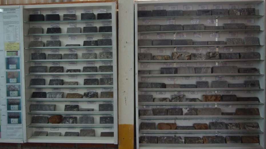
Source: SRK, 2014
Figure 12-1: Photograph of Project Core Lithology Reference Sample Library
Drillhole collar locations are verified against topography, and compared with the survey reports. Downhole survey data are reviewed by an on-site geologist to verify the results.
| 12.2 | Limitations |
SRK did not verify the analytical values in the database with reported values on assay certificates. An additional means to verify analytical zinc and lead grades in the drillhole database could be comparison to visual estimations of sphalerite and galena abundance or to measured specific gravity.
| 76 |
| 12.3 | Opinion on Data Adequacy |
The Project geologists and support staff were diligent about data verification and the quality of the drillhole database. Database validation in preparation for resource estimation has been done by Votorantim. Although SRK did not verify the analytical values in the database with reported values from assay certificates, there were no indicators of erroneous data. SRK believes the degree of organization of the data base and the measures in place to minimize errors in data ensure a high-quality database.
| 77 |
| 13 | Mineral Processing and Metallurgical Testing |
Votorantim retained a metallurgical consultant, Smallvill S.A.C. of Lima, Peru (Smallvill) to perform metallurgical studies on Florida Canyon mineralization types in 2010, 2011 and 2014. All the metallurgical testing programs aimed to produce commercial quality concentrates from a polymetallic lead-zinc mineralization. The tested samples show heads grades significantly higher when compared to other known mineral deposits in the region. SRK has relied heavily on these studies for recovery and cost forecasting to develop cut-off grades for resource reporting.
The Florida Canyon sulfide resource consists of zinc and lead sulfides in a limestone matrix where zinc is in higher proportions than lead. There are no deleterious elements present in concentrates in high enough levels to trigger smelter penalties.
| 13.1 | Testing and Procedures |
A total of eight metallurgical testing documents addressing the metallurgical development for Florida Canyon Project were made available to SRK. All of the metallurgical testwork to date have been executed between 2011 and 2014 (Table 13-1) by Smalvill S.A.C., an independent commercial laboratory based in Lima, Peru.
Table 13-1: Summary of Florida Canyon Metallurgical Test Work
| Report Date | Laboratory | Sample | Sample Type | Test Type |
| 2010 Apr | Smallvill, Lima, Peru | Core composite | Sulfide | Batch scale |
| 2010 May | Smallvill, Lima, Peru | Bulk sample, pilot testing | 1 t ox, 1 t mx, 1 t sul, 1 t of vein and surface material from Shalipayco | Pilot plant |
| 2011 Jul | Smallvill, Lima, Peru | Core composite | Oxide | Batch scale |
| 2011 Aug | Smallvill, Lima, Peru | Core composite | Mixed | Batch scale |
| 2011 Aug | Smallvill, Lima, Peru | Core composite | Sulfide | Batch scale |
| 2011 Aug | Smallvill, Lima, Peru | Core composite | Mixed | Batch scale |
| 2014 Feb | Smallvill, Lima, Peru | San Jorge | Sulfide | Batch scale |
| 2014 Feb | Smallvill, Lima, Peru | Karen Milagros | Sulfide | Batch scale |
Source: SRK, 2017
| 13.2 | Relevant Results |
13.2.1 Mineralogy
Mineralogical analysis of a sulfide composite was conducted on the head sample by X-ray diffraction. The results are provided in Table 13-2. The majority of the sample (80%) consists of calcium and magnesium carbonates from the dolomite matrix, with low iron sulfide content as pyrite, arsenopyrite, and pyrrhotite.
| 78 |
Table 13-2: Mineralogy of Sulfide Composite
| Mineral | Weight % |
| Dolomite | 76.7 |
| Quartz | 4.8 |
| Calcite | 3 |
| Smithsonite | 2 |
| Hemimorphite | 0.2 |
| Pyrite | 3.5 |
| Sphalerite | 7.9 |
| Galena | 1.5 |
| Cerussite | 0.3 |
| Total | 100 |
Source: Smallvill, 2011
A mineralogical analysis by X-ray diffraction was conducted on an oxide composite and the results are provided in Table 13-3.
Table 13-3: Mineralogy of Oxide Composite
| Mineral | Weight % |
| Dolomite | 45.83 |
| Smithsonite | 27.16 |
| Hemimorphite | 10.05 |
| Calcite | 9.1 |
| Quartz | 6.3 |
| Barite | 0.88 |
| Sphalerite | 0.67 |
| Total | 100 |
Source: Smallvill, 2011
Approximately 60% (by volume) of the material is gangue comprised of dolomite, calcite and quartz. These minerals have specific gravities between 2.70 and 2.85 g/cm3. XRD analysis also confirmed the presence of zinc oxides, predominantly as smithsonite, and to a lesser extent, hemimorphite.
13.2.2 Recovery and Concentrate Grades
All the metallurgical testing programs aimed to produce commercial quality concentrates from a polymetallic lead-zinc mineralization. The tested samples show head grades significantly higher when compared to other known mineral deposits in the region. Grades for the eight metallurgical tests for Florida Canyon are shown in Table 13-4 and Figure 13-1.
Head grade in the tested samples ranged from 5.7% Zn total up to 31.7% Zn total. Meanwhile, the oxide zinc ranged from 0% up to 18.4%. Lead grades for the same samples was significantly lower than those of zinc, but still higher than typical mill feed grades in the other MVT deposits in the region ranging 0.5% up to 3.9%.
| 79 |
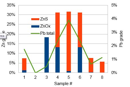
Source: SRK, 2017
Figure 13-1: Metallurgical Sample Results – Zinc and Lead Head Grades
| 80 |
Table 13-4: Metallurgical Tests – Selected Results
| Report Date |
Sample |
Sample Type |
Head Grade |
Grinding |
Pb Concentrate | Zn Concentrate |
Comments | ||||||||||||
| Zn Total | ZnOx | ZnS | ZnOx/ZnT | Pb Total | Pb S | Pb Ox | Ag g/t | Rec. Pb | Grade Pb | Rec. Zn | Rec. ZnT | Rec. ZnS | Grade ZnT | Grade Ag oz/t | |||||
| 2010 Apr | Core composite | Sulfide | 7.52% | 1.4% | 6.1% | 0.19 | 1.72% | 1.26% | 0.46% | 11.6 | 65%-74 mm | 61.20% | 52.60% | 30.00% | 93.10% | 50.60% | 0.95 | ||
|
2010 May |
bulk sample, pilot testing |
1 t ox, 1 t mx, 1 t sul, 1 t of vein and material from Shalipayco |
Results reported below for individual samples | ||||||||||||||||
| 2011 Jul | Core composite | Oxide | 18.36% | 18.4% | 0.0% | 1.00 | 0.47% | 7.8 | 92.40% | 50.00% |
DMS- Flot+Calcine | ||||||||
| 2011 Aug | Core composite | Mixed | 31.25% | 13.2% | 18.1% | 0.42 | 2.38% | 26.5 | 80.90% | 82.30% | DMS-Flot | ||||||||
| 2011 Aug | Core composite | Sulfide | 31.68% | 0.98% | 30.7% | 0.03 | 3.88% | 56.19 | |||||||||||
| 2011 Aug | Core composite | Mixed | 31.25% | 13.2% | 18.1% | 0.42 | 2.38% | 26.5 | 75.00% | 50.00% | 75.00% | 50.00% | Projected flotation only | ||||||
| 2014 Feb | San Jorge | Sulfide | 7.63% | 0.41% | 7.22% | 0.05 | 0.65% | 62%-44 mm | 60.00% | 50.00% | 90.10% | 83.50% | 55.00% | ||||||
| 2014 Feb | Karen Milagros | Sulfide | 5.70% | 0.00% | 5.7% | 0.00 | 1.12% | 80%-44 mm | 72.00% | 50.00% | 80.00% | 49.00% | |||||||
Source: SRK, 2017
| 81 |
Based on the characteristics of the samples tested, SRK is of the opinion that Florida Canyon is best classified as a polymetallic deposit of mixed rock types. It is defined as a polymetallic deposit because all tested samples have varying levels of Zn, Pb, and Ag with good potential of producing a commercial quality zinc concentrate, and lead concentrate. It is defined as mixed rock, because all tested samples present varying levels of oxidization, with zinc oxide and lead oxide appearing to be in similar relative proportion to each other, i.e., ratio ZnOx/ZnT is comparable to PbOx/PbT in the tested samples.
Producing a commercial quality zinc concentrate was easily achieved from the three samples showing a fresh feed ratio of ZnOx/ZnT<0.05, 0.06, and 0.19; all three samples would typically qualify as sulfide ore.
In previous test work, producing a commercial quality zinc concentrate from mixed mineralized material needed to incorporate Dense Media Separation methods (DMS) to maintain high recoveries (80+%). A conventional flotation approach reached commercial quality (about 50%Zn) at the expense of significantly lower metal recovery, with a similar outcome for the lead concentrate. It is SRK’s opinion that conventional flotation should be able to achieve commercial level results (grade and recovery) under improved crushing, grinding, and flotation conditions.
The generation of slimes and ultrafine particles during grinding was constant for all tested samples. In addition to minimizing slimes generation during grinding, there was an opportunity to have adjusted flotation conditions to deal with the loss of recovery to the slimes in a single stage. Removing slimes from the circuit for additional processing is one approach, but another approach could be be more cost-effective, and should be addressed in future testing.
No penalty elements were present in final concentrates in high enough levels to trigger penalties under typical market conditions.
13.2.3 Hardness
Lithology seems to play an important role in the metallurgical performance of the tested samples. Ultrafine particle generation during conventional grinding is high, and it seems to be driven by natural weathering of the rock. The type of mineralization at Florida Canyon can also be observed in existing operating mines in the region.
Results from the rock’s hardness tests were consistent with above observations for all tested samples, see Table 13-5. The Bond Work Index results ranged from 8.54 kWh/tonne to a maximum of
| 12.6 | kWh/tonne which typically qualifies as a soft plant feed. |
Table 13-5: Hardness Test Results
| Sample type | Bond Wi kWh/t |
| Sulfide | 8.54 |
| Oxide | 12.6 |
| Mixed | 11.75 |
| Mixed | 11.75 |
Source: SRK, 2017
| 82 |
13.2.4 Reagents
Common lead and zinc collectors and depressants at varying dosage rates were tested. Details of the test procedures and results are available in Smallvill (2011).
| · | Zinc sulfate as a depressant in lead flotation was determined to not be required; |
| · | The optimum lead flotation pH was determined to be neutral at 7.6; |
| · | Sodium Isopropyl Xanthate, as a lead collector non selective for zinc and iron, at a dosage of 12 g/t was optimal for lead recovery. Higher dosages were required to depress zinc and pyrite; and |
| · | Copper sulfate, coupled with Z-11 to depress pyrite, was tested to activate the zinc in zinc flotation. The optimum dosages were 100 and 20 g/t, respectively. |
| 13.3 | Recovery Projections |
The 2014 recovery testing focused on quantifying recovery as it relates to a measurable zinc oxide:zinc total ratio (ZnO/ZnT). The ratio was determined from 2,813 samples from 423 drillholes with good spatial representation. Depending on their availability and applicability, samples were taken from either coarse rejects or pulp samples. The ratio was estimated into the block model for each metal of interest. SRK developed a sliding-scale recovery curve for each metal using such ratio.
The recovery estimates for Florida Canyon relative to ZnO/ZnT are illustrated in Figure 13-2. Table 13-6 provides the recovery estimates by material type.
Table 13-6: Florida Canyon Metal Recoveries by Material Type
| Parameter | Material Type | ||
| Sulfide | Mixed | Oxide | |
| ZnOx/ZnT Ratio | <= 0.2 | 0.2 to 0.8 | >= 0.8 |
| Zn Recovery | 93% | (-0.8833 (ZnOx/ZnT) + 1.1067)*100 | 40% |
| Pb Recovery | 84% | (-0.7333 (ZnOx/ZnT) + 0.9867)*100 | 40% |
| Ag Recovery | 56% | (-0.4 (ZnOx/ZnT) + 0.64)*100 | 32% |
Source: SRK, 2017

Source: SRK, 2017
Figure 13-2: Florida Canyon Metal Recoveries Relative to ZnO/ZnT Ratio
| 83 |
The average metallurgical recoveries calculated from the mine plan resource for the diluted mineable deposit were 80%, 74% and 52% for zinc, lead, and silver, respectively.
Anticipated concentrate grades used in cut-off grade calculations are 50% for both zinc and lead concentrates, the latter containing associated silver.
| 13.4 | Significant Factors and Recommendations |
SRK sees opportunities for more advanced test work to optimize the metallurgical recovery flow sheet. Previous test work used conventional procedures that were not specific to Florida Canyon material types. Similarly, fines encountered in previous work were not handled appropriately, resulting in sub- optimal flotation conditions and consequently metallurgical results. Sample selection is a key element and more site-specific test work is expected to enhance overall recovery projections at the next level of study.
Considering that the laboratory encountered difficulties in terms of recovery and grade when attempting to reach separation of the zinc and lead minerals into their respective commercial quality concentrates, SRK recommends approaching the selection of samples for the next phase of metallurgical testing considering the following:
| · | The core logging needs to incorporate attributes like clay%, clay type, RQD, oxide content, sulfide content; |
| · | Develop the block model to a level of confidence that identify lithologies, mineralization and alteration throughout the deposit, as well as incorporating all the parameters recorded in during the core logging; |
| · | Assaying of the core should include whole rock analysis. If lithology varies significantly along the core, then the core interval’s length should be adjusted (lengthened or shortened) with the purpose of capturing variability; and |
| · | Collect samples for metallurgical testing representing distinctive zones in the deposit. Representation must be understood as distinctive lithology, mineralization, oxide-to-sulfide ratio. Grade variability should be a secondary criterion when selecting samples, but they must be reasonably close to what a potential mining operation would be able to deliver to the mill. |
Additionally, SRK recommends developing a suitable metallurgical testing program with the assistance of an experienced professional, select a reputable commercial testing facility with proven QA/QC protocols for testing and chemical assaying, and have the testing program directly supervised by a professional that is independent from the testing facility.
| 84 |
| 14 | Mineral Resource Estimate |
Mineral Resource estimation for the Florida Canyon deposit was conducted by Votorantim Metais (Votorantim) in August, 2013 and reported by Mineral Resources Management (MRM), an internal resource modeling group of Votorantim, in December of 2013 (Votorantim, 2013b). In April of 2014, SRK Consulting was contracted by Solitario to audit the MRM resource estimate and prepare a Technical Report on Resources compliant with the guidance of National Instrument 43-101 (NI 43- 101). This detailed independent analysis showed that the modeling methods used by Votorantim in 2013 were valid and produced an appropriate resource estimate. These same methods were used by Votorantim for updating the estimated total zinc and total lead in the preparation of this 2017 resource estimate.
Since the 2013 resource estimate, Millpo has conducted a considerable amount of resampling and metallurgical test work to determine recoverable sulfide and oxide grades for both zinc and lead to better understand recoverable metal in the deposit. This work led to a change in the definition of oxide, transition, and sulfide domains. In the 2013 model, oxide, transition, and sulfide domains were developed based on logged values and then individual metallurgical recoveries were assigned as to each domain. Following the 2014 metallurgical test work, it was determined that a quantitative approach utilizing the ratio of estimated oxide zinc grade to estimated total zinc grade would provide the best representation of the recoverable resource.
Development of the 2017 resource estimate involved two separate grade estimations. First, primary reporting grades were estimated using the same samples as the Votorantim 2013 resource estimate. This estimate assigned the grades from which metal quantities were calculated in the resource. A second resource estimate was conducted using the Votorantim 2014 sample program to assign sulfide and oxide grades for both zinc and lead. These grades were used to calculate a zinc oxide to total zinc ratio (ZnOx/ZnT), which was then used to determine if material was oxide, sulfide, or mixed and to assign a recovery to each modeled block based on that ratio.
The 2014 Votorantim test work included 2,813 intervals from 423 drillholes resampled out of the 2006-2013 drilling campaigns. Depending on their availability and applicability, samples were taken from either coarse rejects or pulp samples. Following a detailed sample validation program, which included 539 control samples (blanks and standards), 238 samples were rejected leaving 2,575 samples to complete this exercise. After the new assays were tabulated they were used to estimate sulfide and oxide grades in the block model.
In preparing the current resource statement, SRK has used engineering experience and informed assumptions to define the appropriate cut-off grade to reflect the mining and processing methods and anticipated costs. This report provides a mineral resource estimate and a classification of resources and reserves reported in accordance with the Canadian Institute of Mining, Metallurgy and Petroleum Standards on Mineral Resources and Reserves: Definitions and Guidelines, November 27, 2010 (CIM). The resource estimate and related geologic model auditing were conducted by, or under the supervision of, J. B. Pennington, M.Sc., C.P.G., of SRK Consulting in Reno, Nevada, who is a Certified Professional Geologist as recognized by the American Institute of Professional Geologists and a Qualified Person as defined by NI 43-101.
| 85 |
The Mineral Resource estimate was based on a 3-D geological model of major structural features and stratigraphically controlled alteration and mineralization. A total of 23 mineral domains were interpreted from mineralized drill intercepts, comprised mostly of 1 m core samples. The project is in metric units. Zinc, lead and silver were estimated into model blocks using Ordinary Kriging (OK). Oxide, Sulfide and Mixed material types were determined based on the ZnOx/ZnT ratio. Density was determined from a large percentage (55%) of measured values, which were used to develop equations for density assignment based on rock type and kriged metal content of the samples.
| 14.1 | Geology and Mineral Domain Modeling |
Florida Canyon is interpreted as a Mississippi Valley Type (MVT) base metal deposit dominated by the zinc and lead sulfides sphalerite and galena. These minerals occur as disseminated and massive replacements hosted in stratigraphically controlled dolomitized limestones of the Upper Triassic to Lower Jurassic Chambara Formation. The deposit is located in karst terrain and, due to locally high degrees of water percolation, shallow sulfide mineralization is locally altered to oxidized carbonate and silicate minerals (smithsonite, hemimorphite and cerussite), collectively referred to in this report as “oxides”. Mineralization occurs both as a set of nearly flat-lying stratiform “mantos” intersected locally by high-angle mineralized zones (e.g.: Sam and San Jorge).
The geological model underpinning the resource estimate was generated in Leapfrog Geo™ 1.3 software using the drillhole database from the drilling campaigns of Cominco and Votorantim.
The underlying carbonate stratigraphy of the Florida Canyon deposit is dome-shaped on a regional scale (Figure 14-1). This geometry was fundamental to the construction of the geological contacts and boundaries of mineralized bodies.
Surfaces that represent stratigraphic units Chambara 1, 2 and 3 were constructed through the contact points of the lithologies in 3-D. The fossil marker beds of Coquina and IBM were identified and used as guide horizons. Then the five main faults that cut the deposit were modeled. The faults were located using a 3-D projection of the geological surface map onto topography in conjunction with fault intercepts as logged in drillholes. The projected geologic surface map is shown in Figure 14-2.
Mineralization is hosted exclusively in dolomitized limestone. The interpreted dolomitized zones between the lower Coquina and the upper IBM marker horizons are shown in tan in Figure 14-3. The extent of dolomite alteration was logged in drillholes and modeled within the five major structural domains.
Mineralized wireframes were built in close relationship to the dolomitization envelope and modified (offset) by internal structures when these offsets were clearly defined. Mineral domains were constructed using a 0.5% zinc cut-off grade. The mineral domain wireframes were built in Leapfrog Geo™ and then imported to MineSight 3D® format for block coding and resource estimation.
In total, 23 individual wireframes were built, which vary from 1 to 12 m in thickness, but most were a minimum of 2 to 3 m thick to address dilution. SRK observed several mineralized intercepts outside of all mineral domains. These were intentionally left out due to insufficient understanding of continuity. Figure 14-4 illustrates the stratiform manto-style mineralization (red, n = 21) and the N-S oriented steeply dipping (70°) Sam and San Jorge zones (blue, n = 2).
| 86 |
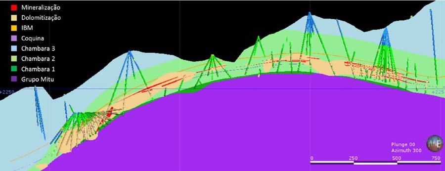
Source: SRK, 2014
Figure 14-1: North-South Longitudinal Section of Geologic Model
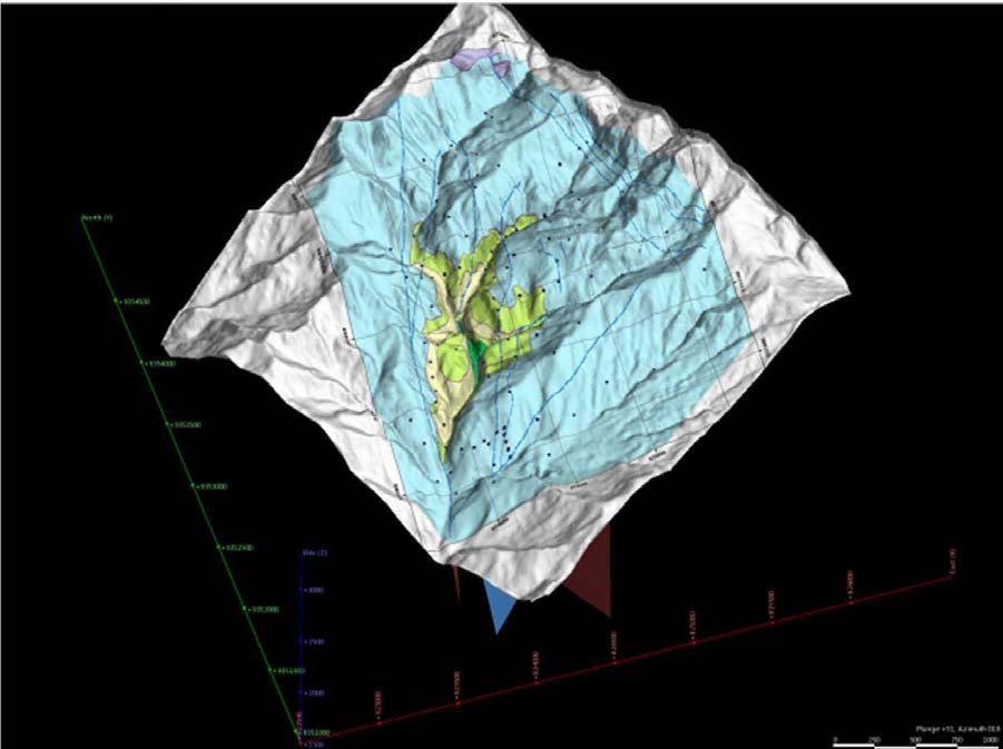
Source: SRK, 2014
Figure 14-2: Florida Canyon Geological and Structural Map Projected on Topography
| 87 |
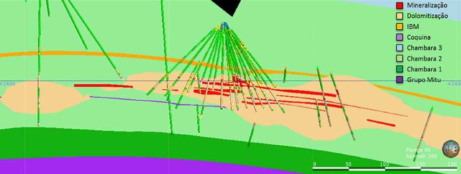
Source: SRK, 2014
Figure 14-3: Geological Cross Section of Karen-Milagros Domain
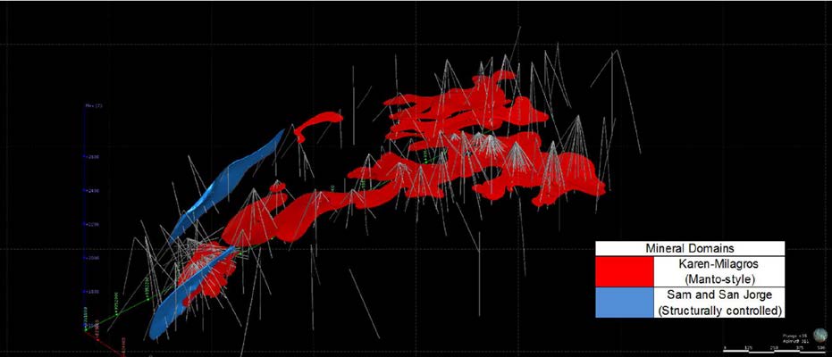
Source: SRK, 2014
Figure 14-4: Oblique View of Mineral Domains
| 14.2 | Drillhole Database |
14.2.1 Database
SRK acquired the project drilling data in MineSight format from Votorantim. The database includes drilling campaigns of two different companies, as well as the resampled data from Votorantim. A total of 82 drillholes were completed by Cominco totaling 24,781 m drilled from 1997 to 2000, and 404 drillholes were completed by Votorantim including 92,499 m drilled from 2006 to 2013. The MineSight drillhole database contains a subset of the relevant portion of this data.
| 88 |
14.2.2 Topography and Sample Locations
Surface topography was generated using a digital aerial survey modified by the points of the drill collars surveyed with a total station instrument.
SRK imported the digital topography into MineSight software and validated drill collar elevations relative to topography.
Downhole surveys were completed by Reflex EZ-Shot by the drillers at 100 m (2010), 50 m (2011) and 20 m (2012/13) down-hole spacings. The records of these are kept digitally at the core facility and were verified during the SRK site visit.
14.2.3 Oxidation Classification in Drillhole Logging
Oxidation classification of core sample intervals has previously been determined visually according to the abundance of sphalerite and galena, as well as according to hemimorphite and smithsonite phases. With the dedicated 2014 metallurgical sampling program, the ratio of estimated zinc oxide to zinc total ratio is based on the Votorantim grade estimation which has superseded the visual logging of sulfides. In this resource estimate, any blocks with a ZnOx/ZnT ratio less than 0.2 are considered sulfide, a ZnOx/ZnT ratio between 0.2 and 0.8 is considered mixed, and a ZnOx/ZnT ratio greater than
0.8 is considered oxide.
| 14.3 | Drilling Data Analysis |
The source database contains 486 diamond core drillholes totaling 117,280.25 m. There are 47,970 intervals with geological description, from which 23,863 were sampled and have chemical analyses for zinc. Fewer have analyses for lead and silver, 13,780 and 23,699 intervals, respectively. Approximately 91% of the sample intervals had measured core recovery and the core recovery averaged 98.3%. The Votorantim MineSight drillhole database used to build this resource model contains a subset of 441 holes totaling 109762.2 m of drilling, from which, 24,244 intervals have chemical analyses for zinc. The raw assay statistics for the samples in the database used to develop the resource are presented in Table 14-1.
For grade estimation for the manto bodies, only the intervals that fell within the Manto solids were used. Intervals that were drilled within a given manto wireframe were flagged with its corresponding code and then composited at fixed lengths honoring those flags. Table 14-2 includes the summary statistics for the 2,875 assay intervals flagged with a Manto code.
Table 14-1: Statistics of Raw Assays – All Intervals
| Item | Item Description | Weighted by | Valid Intervals | Total Intervals | Min | Max | Mean | Variance | Standard Deviation |
| ZNVOT | Zn % Total (VM-2013) | Length | 24244 | 27737 | 0.00 | 57.31 | 1.46 | 31.87 | 5.65 |
| ZNTOT | Zn % Total (VM-2017) | Length | 2880 | 27737 | 0.00 | 56.27 | 7.32 | 124.19 | 11.14 |
| ZNOXS | Zn % Oxide (VM-2017) | Length | 2880 | 27737 | 0.00 | 48.22 | 2.15 | 32.99 | 5.74 |
| ZNSFS | Zn % Sulfide (VM-2017) | Length | 2880 | 27737 | 0.00 | 53.84 | 5.17 | 99.01 | 9.95 |
| PBVOT | Pb % Total(VM-2013) | Length | 24244 | 27737 | 0.00 | 44.60 | 0.21 | 1.65 | 1.29 |
| PBTOT | Pb % Total (VM-2017) | Length | 2880 | 27737 | 0.01 | 38.95 | 0.99 | 6.89 | 2.62 |
| PBOXS | Pb % Oxide (VM-2017) | Length | 2880 | 27737 | 0.01 | 13.37 | 0.27 | 0.55 | 0.74 |
| PBSFS | Pb % Sulfide (VM-2017) | Length | 2880 | 27737 | 0.00 | 27.06 | 0.72 | 4.82 | 2.20 |
| AGVOT | Ag ppm (VM-2013) | Length | 24080 | 27737 | 0.00 | 258.00 | 2.63 | 117.33 | 10.83 |
| DENS | Density (SG) | - | 6585 | 27737 | 1.88 | 4.86 | 2.80 | 0.05 | 0.23 |
Source: SRK, 2017
| 89 |
Table
14-2: Statistics of Raw Assays – Manto Intervals Only
| Assay Item ID | Item Description | Weighted by | Valid Data | Total Data | Min | Max | Mean | Variance | Standard Deviation |
| ZNVOT | Zn % Total (Votorantim) | Length | 2875 | 2875 | 0.00 | 57.31 | 9.79 | 149.91 | 12.24 |
| ZNTOT | Zn % Total (VM-2017) | Length | 2228 | 2875 | 0.00 | 56.27 | 9.47 | 141.38 | 11.89 |
| ZNOXS | Zn % Oxide (VM-2017) | Length | 2228 | 2875 | 0.00 | 48.22 | 2.77 | 41.39 | 6.43 |
| ZNSFS | Zn % Sulfide (VM-2017) | Length | 2228 | 2875 | 0.00 | 53.84 | 6.70 | 118.44 | 10.88 |
| PBVOT | Pb % Total (Votorantim) | Length | 2875 | 2875 | 0.00 | 40.84 | 1.36 | 9.21 | 3.04 |
| PBTOT | Pb % Total (VM-2017) | Length | 2228 | 2875 | 0.01 | 38.95 | 1.26 | 8.54 | 2.92 |
| PBOXS | Pb % Oxide (VM-2017) | Length | 2228 | 2875 | 0.01 | 13.37 | 0.34 | 0.69 | 0.83 |
| PBSFS | Pb % Sulfide (VM-2017) | Length | 2228 | 2875 | 0.00 | 27.06 | 0.92 | 6.04 | 2.46 |
| AGVOT | Ag ppm (VM-2013) | Length | 2795 | 2875 | 0.09 | 258.00 | 14.14 | 642.66 | 25.35 |
| DENS | Density (SG) | - | 1578 | 2875 | 1.88 | 4.86 | 2.97 | 0.12 | 0.35 |
Source: SRK, 2017
14.3.1 Capping
SRK’s approach for capping was to analyze raw assay data and identify statistical outliers in each element of economic interest. For this analysis, those assays contained within the interpreted mineral domains were analyzed. Histograms and cumulative frequency graphs were prepared for zinc, lead and silver variability. In the variability charts, a predominantly log-normal distribution was observed, which does not show clear inflections, signifying a single population distribution and not separate high and low-grade populations. For these reasons, SRK concludes zinc, lead and silver do not require capping. The single anomalously high zinc value (57.3%) in the database in hole V_465 (116.1 to
117.1 m) was inspected in 3-D and found to be consistent with and part of a 10 m high grade interval in an area of the San Jorge mineral domain supported by high-grade intercepts in neighboring drillholes.
During grade estimation, Votorantim elected to use a sliding-scale percentile method for capping relative to search pass, in a multi-pass estimation process. SRK has reviewed the Votorantim approach and considers it appropriate if not slightly conservative relative to our analysis of the grade populations.
14.3.2 Compositing
In the software, the raw assay database was back-coded using the mineral domain (Manto) wireframes described in Section 14.1, resulting in 2,875 intercepts inside the mineralized shapes. The coded samples were then composited to the length of 1.5 m generating 1,931 composited samples out of 2,875 original samples. Intervals at the end of a Manto domain less than 0.75 m in length were merged into the previous interval. As numerous analyses were run using this data set in addition to generating the resource estimate, several items were added to the data files with different IDs. For clarity, Table 14-3 includes the item ID’s used in the drillholes and their corresponding composite ID and description including the company sampling program associated with the source data. Table 14-4 provides summary statistics for all Composites within the manto wireframes.
| 90 |
Table 14-3: Item ID’s and Descriptions
| Assay Item ID | Composite Item ID | Description |
| ZNVOT | ZNVOT | Total Zinc Grade - 2013 Sampling |
| ZNTOT | ZNT0 | Total Zinc Grade (ZNOXS + ZNSFS) |
| ZNOXS | ZNO0 | Oxide Zinc Grade - 2014 Sampling |
| ZNSFS | ZNS0 | Sulfide Zinc Grade - 2014 Sampling |
| PBVOT | PBVOT | Total Lead Grade - 2013 Sampling |
| PBTOT | PBT0 | Total Lead Grade (PBOXS + PBSFS) |
| PBOXS | PBO0 | Oxide Lead Grade - 2014 Sampling |
| PBSFS | PBS0 | Sulfide Lead Grade - 2014 Sampling |
| AGVOT | AGVOT | Total Silver Grade - 2013 Sampling |
| DENS | DENS | Density - 2013 Sampling |
| LITO | LITO | Logged Lithology – 2013 |
| MANTO | MANTO | Manto Zone Flag |
Source: SRK, 2017
Table 14-4: Statistics of All Composites Inside Mantos
|
Composite Item ID |
Item Description |
Weighted by |
Valid Data |
Total Data |
Min | Max | Mean | Variance |
Standard Deviation |
| ZNVOT |
Zn % Total (2013) |
Length | 1931 | 1931 | 0.01 | 56.49 | 9.60 | 115.80 | 10.76 |
| ZNT0 |
Zn % Total (2014) |
Length | 1931 | 1931 | 0.01 | 55.63 | 9.26 | 113.22 | 10.64 |
| ZNOX0 |
Zn % Oxide (2014) |
Length | 1931 | 1931 | 0.00 | 45.00 | 2.95 | 37.39 | 6.11 |
| ZNSF0 |
Zn % Sulfide (2014) |
Length | 1931 | 1931 | 0.00 | 50.56 | 6.31 | 91.72 | 9.58 |
| PBVOT |
Pb % Total (2013) |
Length | 1931 | 1931 | 0.00 | 21.98 | 1.33 | 6.83 | 2.61 |
| PBT0 |
Pb % Total (2014) |
Length | 1931 | 1931 | 0.00 | 21.36 | 1.26 | 6.42 | 2.53 |
| PBOX0 |
Pb % Oxide (2014) |
Length | 1931 | 1931 | 0.00 | 9.07 | 0.38 | 0.62 | 0.79 |
| PBSF0 |
Pb % Sulfide (2014) |
Length | 1931 | 1931 | 0.00 | 20.31 | 0.88 | 4.25 | 2.06 |
| AGVOT |
Ag ppm (2013) |
Length | 1862 | 1931 | 0.12 | 161.67 | 13.84 | 494.37 | 22.23 |
| DENS |
Density (SG) |
- | 1064 | 1931 | 2.06 | 4.66 | 2.96 | 0.10 | 0.32 |
Source: SRK, 2017. Separate sampling programs are identified in the Item description (Votorantim-2013 or Votorantim-2014 )
| 14.4 | Density |
Density is calculated in the model using the following equation: DENSITY = 2.786 + ( 0.016 * ZN ) + ( 0.037 * PB)
SRK checked the assigned density values in the model and found the density to be defined by this equation. Spot checks for block values show a very slight discrepancy for some blocks, however, a global validation check showed these discrepancies amount to a resource density change of less than 0.01%. SRK is of the opinion that, due to the minimal impact this difference has on the reported resource tonnage, this discrepancy is not material to the resource and considers the density assignment to be valid.
| 91 |
| 14.5 | Variogram Analysis and Modeling |
In preparing the previous 2014 Resource Estimate, an extensive review of the deposit variography was conducted. Separate semi-variograms, normalized to a sill of 1.0 were generated using samples from both the high-angle structurally controlled domains (Sam, San Jorge) and the flat stratiform mineralized mantos (Karen-Milagros). In preparing this 2017 resource estimate, a similar exercise was conducted by Votorantim, with the addition of Block 1, Block 2 and Block3 domains that were designed to capture the different structural trends of the deposit (Figure 14-6).
As the underlying total lead and zinc grade data being estimated has not changed between the current and the 2014 resource estimates, SRK did not repeat this exercise. Rather, the search ranges and directions used for this estimation run were compared to those used in the 2014 Resource Estimate and compared to the underlying geology. Based on that review, SRK finds that the search criteria used for this modeling effort are appropriate, and well supported by the underlying geology.
Details of the variography are presented in Table 14-8.
| 14.6 | Block Model |
14.6.1 Model Specifications
The block model was constructed in UTM metric coordinates using MineSightTM modeling software. A block size of 6 m wide x 6 m long x 3 m high was used. Horizontal block dimensions were determined based on drill sample spacing and the block height was selected to maintain the resolution needed for mine planning. The parameters used in the generation of the block model are summarized in Table 14-5. Field descriptions of model items are provided in Table 14-6. SRK added items to facilitate engineering as outlined in Table 14-7.
Table 14-5: Block Model Specifications
| Coordinate | Min | Max | Size | No. Blocks |
| Easting | 823700 | 825650 | 6 | 325 |
| Northing | 9351680 | 9354422 | 6 | 457 |
| Elevation | 1550 | 3161 | 3 | 537 |
Source: SRK 2017
Table 14-6: Block Model Item Descriptions
| Item | Description |
| TOPO | Percentage of the block below the topography |
| ZNOKC | OK Estimate Zinc Oxides from 2014 Sampling |
| ZNSKC | OK Estimate Zinc Sulfides from 2014Sampling |
| PBOKC | OK Estimate Lead Oxides from 2014Sampling |
| PBSKC | OK Estimate Lead Sulfides from 2014 Sampling |
| DENS | Density |
| CATGE | Resource Categorization (1=measured, 2=indicated, 3=inferred) |
| MANTO | Manto Zone Code (Includes Vertical Structures) |
| MANT% | Percentage of each block within the Manto Solids |
| BLOCK | Interpolation Sectors for Varying Search Directions |
| ZNVKC | OK Estimate of Zinc from the Votorantim 2013 sampling |
| PBVKC | OK Estimate of Lead from the Votorantim 2013 sampling |
| AGVKC | Silver Interpolation by OK of Votorantim 2013 sampling |
| FEVKC | Interpolation of Iron by OK of the sampling of Votorantim 2013 |
| RATZN | Zinc Oxide Ratio: ZNOKC / (ZNOKC + ZNSKC) |
| RATPB | Oxide Lead Ratio: PBOKC / (PBOKC + PBSKC) |
| ZNTKV | Copy of ZNVKC (Estimated Votorantim 2013 Grade) |
| ZNSKV | Value of Zn sulfides: ZNTKV * (1-RATZN) |
| ZNOKV | Value of Zn oxides: ZNTKV * (RATZN) |
| PBTKV | Copy of PBVKC (Estimated Votorantim 2013 Grade) |
| PBSKV | PB sulphide value: PBTKV * (1-RATPB) |
| PBOKV | Value of PB oxides: PBTKV * (RATPB) |
Source: Votorantim, 2017, edited by SRK, 2017
Table 14-7: Additional SRK Block Model Item Descriptions
| Item | Description |
| ZNREC | Zinc Recovery |
| PBREC | Lead Recovery |
| AGREC | Silver Recovery |
| ZNTRC | Recovered Total Zinc Grade (ZNVKC * ZNREC) |
| PBTRC | Recovered Total Lead Grade (PBVKC * PBREC) |
| AGVRC | Recovered Total Ag Grade (AGVKC * AGREC) |
| ZNREQ | Recovered Equivalent Zinc Grade |
| ZNEQ | Equivalent Zinc Grade (ZNREQ / ZNREC x 100) |
| SGSRK | SRK Desnity Check Item |
| OTFLG | Material Type from ZnOx/ZnT Ratio (1=Oxide, 2=Mixed, 3=Sulfide) |
Source: SRK, 2017
14.6.2 Model Construction
The two sets of mineralized wireframes were imported and coded into the MANTO item in the MineSight model. Both the code of each solid and the percentage of each solid were stored in the blocks.
Given the uneven distribution of holes and the domal shape of the deposit, the model was divided into three areas based on the orientation of the mineralized shapes. The areas, flagged in the BLOCK item, were then used to control the anisotropic search direction used during grade estimation. The two vertical structures, Sam and Sam Jorge, we estimated independently. The block codes stored in the model are shown in Figure 14-5.
| 92 |
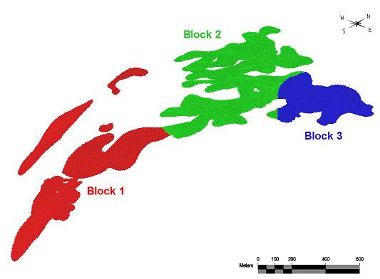
Source: SRK, 2017
Figure 14-5: Estimation BLOCK Zones
| 14.7 | Grade Estimation |
The strategy for block grade estimation was the same for all variables considered in each of the mineral domains. Grades in each domain were estimated only with composites coded to that domain. The estimate for zinc, lead, and silver was performed by four pass Ordinary Kriging for both the Votorantim 2014 and Votorantim 2017 grade items. The first pass used a long search distance intended to fill the mineral domains with grade. This pass was capped at the 95th percentile to prevent proliferation of high grades during the estimate. For the second and third passes, distances were shortened with each pass and the grade cap adjusted to the 97th and 99th percentiles, respectively. The fourth pass ran with the shortest search distance and high grades were not capped. Each pass was reviewed for each estimation domain and adjusted as necessary to validate compared to input composites.
Details of the grade estimation by Block and Manto are presented in Table 14-8.
| 93 |
Table 14-8: Variogram and Grade Estimation Parameters
|
Block 1 Estimation Parameters for Total Zinc Grade Using Votorantim Sample Data |
||||||||||||||||||||||||||||||||||||||||||||
| Block Flag | 1 | 1 | 1 | 1 | 1 | 1 | 1 | 1 | 1 | 1 | 1 | 1 | 1 | 1 | 1 | 1 | 1 | 1 | 1 | 1 | 1 | 1 | 1 | 1 | 1 | 1 | 1 | 1 | 1 | 1 | 1 | 1 | 1 | 1 | 1 | 1 | 1 | 1 | 1 | 1 | 1 | 1 | 1 | 1 |
| Manto Flag | 3 | 3 | 3 | 3 | 6 | 6 | 6 | 6 | 12 | 12 | 12 | 12 | 14 | 14 | 14 | 14 | 15 | 15 | 15 | 15 | 16 | 16 | 16 | 16 | 17 | 17 | 17 | 17 | 18 | 18 | 18 | 18 | 19 | 19 | 19 | 19 | 20 | 20 | 20 | 20 | 21 | 21 | 21 | 21 |
| Min Composites to Estimate | 1 | 1 | 3 | 2 | 1 | 1 | 3 | 2 | 1 | 1 | 3 | 2 | 1 | 1 | 3 | 2 | 1 | 1 | 3 | 2 | 1 | 1 | 3 | 2 | 1 | 1 | 3 | 2 | 1 | 1 | 3 | 2 | 1 | 1 | 3 | 2 | 1 | 1 | 3 | 2 | 1 | 1 | 3 | 2 |
| Max Composites to Estimate | 4 | 6 | 8 | 12 | 4 | 6 | 8 | 12 | 4 | 6 | 8 | 12 | 4 | 6 | 8 | 12 | 4 | 6 | 8 | 12 | 4 | 6 | 8 | 12 | 4 | 6 | 8 | 12 | 4 | 6 | 8 | 12 | 4 | 6 | 8 | 12 | 4 | 6 | 8 | 12 | 4 | 6 | 8 | 12 |
| Max Composites Per Hole | 2 | 2 | 2 | 2 | 2 | 2 | 2 | 2 | 2 | 2 | 2 | 2 | 2 | 2 | 2 | 2 | 2 | 2 | 2 | 2 | 2 | 2 | 2 | 2 | 2 | 2 | 2 | 2 | 2 | 2 | 2 | 2 | 2 | 2 | 2 | 2 | 2 | 2 | 2 | 2 | 2 | 2 | 2 | 2 |
| Composite Item | ZNVOT | ZNVOT | ZNVOT | ZNVOT | ZNVOT | ZNVOT | ZNVOT | ZNVOT | ZNVOT | ZNVOT | ZNVOT | ZNVOT | ZNVOT | ZNVOT | ZNVOT | ZNVOT | ZNVOT | ZNVOT | ZNVOT | ZNVOT | ZNVOT | ZNVOT | ZNVOT | ZNVOT | ZNVOT | ZNVOT | ZNVOT | ZNVOT | ZNVOT | ZNVOT | ZNVOT | ZNVOT | ZNVOT | ZNVOT | ZNVOT | ZNVOT | ZNVOT | ZNVOT | ZNVOT | ZNVOT | ZNVOT | ZNVOT | ZNVOT | ZNVOT |
| Model Item | ZNVKC | ZNVKC | ZNVKC | ZNVKC | ZNVKC | ZNVKC | ZNVKC | ZNVKC | ZNVKC | ZNVKC | ZNVKC | ZNVKC | ZNVKC | ZNVKC | ZNVKC | ZNVKC | ZNVKC | ZNVKC | ZNVKC | ZNVKC | ZNVKC | ZNVKC | ZNVKC | ZNVKC | ZNVKC | ZNVKC | ZNVKC | ZNVKC | ZNVKC | ZNVKC | ZNVKC | ZNVKC | ZNVKC | ZNVKC | ZNVKC | ZNVKC | ZNVKC | ZNVKC | ZNVKC | ZNVKC | ZNVKC | ZNVKC | ZNVKC | ZNVKC |
| 1st Variogram Structure Type | SPH | SPH | SPH | SPH | SPH | SPH | SPH | SPH | SPH | SPH | SPH | SPH | SPH | SPH | SPH | SPH | SPH | SPH | SPH | SPH | SPH | SPH | SPH | SPH | SPH | SPH | SPH | SPH | SPH | SPH | SPH | SPH | SPH | SPH | SPH | SPH | SPH | SPH | SPH | SPH | SPH | SPH | SPH | SPH |
| 2nd Variogram Structure Type | SPH | SPH | SPH | SPH | SPH | SPH | SPH | SPH | SPH | SPH | SPH | SPH | SPH | SPH | SPH | SPH | SPH | SPH | SPH | SPH | SPH | SPH | SPH | SPH | SPH | SPH | SPH | SPH | SPH | SPH | SPH | SPH | SPH | SPH | SPH | SPH | SPH | SPH | SPH | SPH | SPH | SPH | SPH | SPH |
| Variogram Nugget | 0.35 | 0.35 | 0.35 | 0.35 | 0.35 | 0.35 | 0.35 | 0.35 | 0.35 | 0.35 | 0.35 | 0.35 | 0.35 | 0.35 | 0.35 | 0.35 | 0.35 | 0.35 | 0.35 | 0.35 | 0.35 | 0.35 | 0.35 | 0.35 | 0.35 | 0.35 | 0.35 | 0.35 | 0.35 | 0.35 | 0.35 | 0.35 | 0.35 | 0.35 | 0.35 | 0.35 | 0.35 | 0.35 | 0.35 | 0.35 | 0.35 | 0.35 | 0.35 | 0.35 |
| 1st Variogram Sill | 0.42 | 0.42 | 0.42 | 0.42 | 0.42 | 0.42 | 0.42 | 0.42 | 0.42 | 0.42 | 0.42 | 0.42 | 0.42 | 0.42 | 0.42 | 0.42 | 0.42 | 0.42 | 0.42 | 0.42 | 0.42 | 0.42 | 0.42 | 0.42 | 0.42 | 0.42 | 0.42 | 0.42 | 0.42 | 0.42 | 0.42 | 0.42 | 0.42 | 0.42 | 0.42 | 0.42 | 0.42 | 0.42 | 0.42 | 0.42 | 0.42 | 0.42 | 0.42 | 0.42 |
| 2nd Variogram Sill | 0.23 | 0.23 | 0.23 | 0.23 | 0.23 | 0.23 | 0.23 | 0.23 | 0.23 | 0.23 | 0.23 | 0.23 | 0.23 | 0.23 | 0.23 | 0.23 | 0.23 | 0.23 | 0.23 | 0.23 | 0.23 | 0.23 | 0.23 | 0.23 | 0.23 | 0.23 | 0.23 | 0.23 | 0.23 | 0.23 | 0.23 | 0.23 | 0.23 | 0.23 | 0.23 | 0.23 | 0.23 | 0.23 | 0.23 | 0.23 | 0.23 | 0.23 | 0.23 | 0.23 |
| Variogram Structure 1 Major Range (m) | 7 | 7 | 7 | 7 | 7 | 7 | 7 | 7 | 7 | 7 | 7 | 7 | 7 | 7 | 7 | 7 | 7 | 7 | 7 | 7 | 7 | 7 | 7 | 7 | 7 | 7 | 7 | 7 | 7 | 7 | 7 | 7 | 7 | 7 | 7 | 7 | 7 | 7 | 7 | 7 | 7 | 7 | 7 | 7 |
| Variogram Structure 1 Semi- Major Range (m) | 5 | 5 | 5 | 5 | 5 | 5 | 5 | 5 | 5 | 5 | 5 | 5 | 5 | 5 | 5 | 5 | 5 | 5 | 5 | 5 | 5 | 5 | 5 | 5 | 5 | 5 | 5 | 5 | 5 | 5 | 5 | 5 | 5 | 5 | 5 | 5 | 5 | 5 | 5 | 5 | 5 | 5 | 5 | 5 |
| Variogram Structure 1 Minor Range (m) | 5 | 5 | 5 | 5 | 5 | 5 | 5 | 5 | 5 | 5 | 5 | 5 | 5 | 5 | 5 | 5 | 5 | 5 | 5 | 5 | 5 | 5 | 5 | 5 | 5 | 5 | 5 | 5 | 5 | 5 | 5 | 5 | 5 | 5 | 5 | 5 | 5 | 5 | 5 | 5 | 5 | 5 | 5 | 5 |
| Variogram Structure 2 Major Range (m) | 22 | 22 | 22 | 22 | 22 | 22 | 22 | 22 | 22 | 22 | 22 | 22 | 22 | 22 | 22 | 22 | 22 | 22 | 22 | 22 | 22 | 22 | 22 | 22 | 22 | 22 | 22 | 22 | 22 | 22 | 22 | 22 | 22 | 22 | 22 | 22 | 22 | 22 | 22 | 22 | 22 | 22 | 22 | 22 |
| Variogram Structure 2 Semi- Major Range (m) | 17 | 17 | 17 | 17 | 17 | 17 | 17 | 17 | 17 | 17 | 17 | 17 | 17 | 17 | 17 | 17 | 17 | 17 | 17 | 17 | 17 | 17 | 17 | 17 | 17 | 17 | 17 | 17 | 17 | 17 | 17 | 17 | 17 | 17 | 17 | 17 | 17 | 17 | 17 | 17 | 17 | 17 | 17 | 17 |
| Variogram Structure 2 Minor Range (m) | 10 | 10 | 10 | 10 | 10 | 10 | 10 | 10 | 10 | 10 | 10 | 10 | 10 | 10 | 10 | 10 | 10 | 10 | 10 | 10 | 10 | 10 | 10 | 10 | 10 | 10 | 10 | 10 | 10 | 10 | 10 | 10 | 10 | 10 | 10 | 10 | 10 | 10 | 10 | 10 | 10 | 10 | 10 | 10 |
| Variogram Major Direction (deg) | 28 | 28 | 28 | 28 | 28 | 28 | 28 | 28 | 347 | 347 | 347 | 347 | 20 | 20 | 20 | 20 | 40 | 40 | 40 | 40 | 22 | 22 | 22 | 22 | 28 | 28 | 28 | 28 | 28 | 28 | 28 | 28 | 13 | 13 | 13 | 13 | 52 | 52 | 52 | 52 | 35 | 35 | 35 | 35 |
| Variogram Semi-Major direction (deg) | 18 | 18 | 18 | 18 | 22 | 22 | 22 | 22 | 30 | 30 | 30 | 30 | 8 | 8 | 8 | 8 | 18 | 18 | 18 | 18 | 43 | 43 | 43 | 43 | 41 | 41 | 41 | 41 | 41 | 41 | 41 | 41 | 41 | 41 | 41 | 41 | 29 | 29 | 29 | 29 | 36 | 36 | 36 | 36 |
| Variogram Minor Direction (deg) | 0 | 0 | 0 | 0 | 0 | 0 | 0 | 0 | 0 | 0 | 0 | 0 | 0 | 0 | 0 | 0 | 0 | 0 | 0 | 0 | 0 | 0 | 0 | 0 | 0 | 0 | 0 | 0 | 0 | 0 | 0 | 0 | 0 | 0 | 0 | 0 | 0 | 0 | 0 | 0 | 0 | 0 | 0 | 0 |
| Major Search Ellipse Range (m) | 220 | 132 | 88 | 44 | 400 | 132 | 88 | 44 | 150 | 132 | 88 | 44 | 350 | 132 | 88 | 44 | 150 | 132 | 88 | 44 | 150 | 132 | 88 | 44 | 150 | 132 | 88 | 44 | 150 | 132 | 88 | 44 | 150 | 132 | 88 | 44 | 150 | 132 | 88 | 44 | 150 | 132 | 88 | 44 |
| Semi-Major Search Ellipse Range (m) | 170 | 102 | 68 | 34 | 250 | 102 | 68 | 34 | 150 | 102 | 68 | 34 | 250 | 102 | 68 | 34 | 150 | 102 | 68 | 34 | 150 | 102 | 68 | 34 | 150 | 102 | 68 | 34 | 150 | 102 | 68 | 34 | 150 | 102 | 68 | 34 | 150 | 102 | 68 | 34 | 150 | 102 | 68 | 34 |
| Minor Search Ellipse Range (m) | 40 | 30 | 20 | 10 | 40 | 30 | 20 | 10 | 40 | 30 | 20 | 10 | 40 | 30 | 20 | 10 | 40 | 30 | 20 | 10 | 40 | 30 | 20 | 10 | 40 | 30 | 20 | 10 | 40 | 30 | 20 | 10 | 40 | 30 | 20 | 10 | 40 | 30 | 20 | 10 | 40 | 30 | 20 | 10 |
| Cap on Zinc Grade (%) | 15 | 22 | 38 | 15 | 22 | 38 | 15 | 22 | 38 | 15 | 22 | 38 | 15 | 22 | 38 | 15 | 22 | 38 | 15 | 22 | 38 | 15 | 22 | 38 | 15 | 22 | 38 | 15 | 22 | 38 | 15 | 22 | 38 | |||||||||||
| Source: Votorantim 2017 | ||||||||||||||||||||||||||||||||||||||||||||
| Block 2 Estimation Parameters for Total Zinc Grade Using Votorantim Sample Data | ||||||||||||||||||||||||||||||||||||||||||||
| Block Flag | 2 | 2 | 2 | 2 | 2 | 2 | 2 | 2 | 2 | 2 | 2 | 2 | 2 | 2 | 2 | 2 | 2 | 2 | 2 | 2 | 2 | 2 | 2 | 2 | 2 | 2 | 2 | 2 | 2 | 2 | 2 | 2 | 2 | 2 | 2 | 2 | 2 | 2 | 2 | 2 | ||||
| Manto Flag | 2 | 2 | 2 | 2 | 3 | 3 | 3 | 3 | 4 | 4 | 4 | 4 | 6 | 6 | 6 | 6 | 7 | 7 | 7 | 7 | 8 | 8 | 8 | 8 | 9 | 9 | 9 | 9 | 10 | 10 | 10 | 10 | 11 | 11 | 11 | 11 | 13 | 13 | 13 | 13 | ||||
| Min Composites to Estimate | 1 | 1 | 3 | 2 | 1 | 1 | 3 | 2 | 1 | 1 | 3 | 2 | 1 | 1 | 3 | 2 | 1 | 1 | 3 | 2 | 1 | 1 | 3 | 2 | 1 | 1 | 3 | 2 | 1 | 1 | 3 | 2 | 1 | 1 | 3 | 2 | 1 | 1 | 3 | 2 | ||||
| Max Composites to Estimate | 4 | 6 | 8 | 12 | 4 | 6 | 8 | 12 | 4 | 6 | 8 | 12 | 4 | 6 | 8 | 12 | 4 | 6 | 8 | 12 | 4 | 6 | 8 | 12 | 4 | 6 | 8 | 12 | 4 | 6 | 8 | 12 | 4 | 6 | 8 | 12 | 4 | 6 | 8 | 12 | ||||
| Max Composites Per Hole | 2 | 2 | 2 | 2 | 2 | 2 | 2 | 2 | 2 | 2 | 2 | 2 | 2 | 2 | 2 | 2 | 2 | 2 | 2 | 2 | 2 | 2 | 2 | 2 | 2 | 2 | 2 | 2 | 2 | 2 | 2 | 2 | 2 | 2 | 2 | 2 | 2 | 2 | 2 | 2 | ||||
| Composite Item | ZNVOT | ZNVOT | ZNVOT | ZNVOT | ZNVOT | ZNVOT | ZNVOT | ZNVOT | ZNVOT | ZNVOT | ZNVOT | ZNVOT | ZNVOT | ZNVOT | ZNVOT | ZNVOT | ZNVOT | ZNVOT | ZNVOT | ZNVOT | ZNVOT | ZNVOT | ZNVOT | ZNVOT | ZNVOT | ZNVOT | ZNVOT | ZNVOT | ZNVOT | ZNVOT | ZNVOT | ZNVOT | ZNVOT | ZNVOT | ZNVOT | ZNVOT | ZNVOT | ZNVOT | ZNVOT | ZNVOT | ||||
| Model Item | ZNVKC | ZNVKC | ZNVKC | ZNVKC | ZNVKC | ZNVKC | ZNVKC | ZNVKC | ZNVKC | ZNVKC | ZNVKC | ZNVKC | ZNVKC | ZNVKC | ZNVKC | ZNVKC | ZNVKC | ZNVKC | ZNVKC | ZNVKC | ZNVKC | ZNVKC | ZNVKC | ZNVKC | ZNVKC | ZNVKC | ZNVKC | ZNVKC | ZNVKC | ZNVKC | ZNVKC | ZNVKC | ZNVKC | ZNVKC | ZNVKC | ZNVKC | ZNVKC | ZNVKC | ZNVKC | ZNVKC | ||||
| 1st Variogram Structure Type | SPH | SPH | SPH | SPH | SPH | SPH | SPH | SPH | SPH | SPH | SPH | SPH | SPH | SPH | SPH | SPH | SPH | SPH | SPH | SPH | SPH | SPH | SPH | SPH | SPH | SPH | SPH | SPH | SPH | SPH | SPH | SPH | SPH | SPH | SPH | SPH | SPH | SPH | SPH | SPH | ||||
| 2nd Variogram Structure Type | SPH | SPH | SPH | SPH | SPH | SPH | SPH | SPH | SPH | SPH | SPH | SPH | SPH | SPH | SPH | SPH | SPH | SPH | SPH | SPH | SPH | SPH | SPH | SPH | SPH | SPH | SPH | SPH | SPH | SPH | SPH | SPH | SPH | SPH | SPH | SPH | SPH | SPH | SPH | SPH | ||||
| Variogram Nugget | 0.35 | 0.35 | 0.35 | 0.35 | 0.35 | 0.35 | 0.35 | 0.35 | 0.35 | 0.35 | 0.35 | 0.35 | 0.35 | 0.35 | 0.35 | 0.35 | 0.35 | 0.35 | 0.35 | 0.35 | 0.35 | 0.35 | 0.35 | 0.35 | 0.35 | 0.35 | 0.35 | 0.35 | 0.35 | 0.35 | 0.35 | 0.35 | 0.35 | 0.35 | 0.35 | 0.35 | 0.35 | 0.35 | 0.35 | 0.35 | ||||
| 1st Variogram Sill | 0.4 | 0.4 | 0.4 | 0.4 | 0.4 | 0.4 | 0.4 | 0.4 | 0.4 | 0.4 | 0.4 | 0.4 | 0.4 | 0.4 | 0.4 | 0.4 | 0.4 | 0.4 | 0.4 | 0.4 | 0.4 | 0.4 | 0.4 | 0.4 | 0.4 | 0.4 | 0.4 | 0.4 | 0.4 | 0.4 | 0.4 | 0.4 | 0.4 | 0.4 | 0.4 | 0.4 | 0.4 | 0.4 | 0.4 | 0.4 | ||||
| 2nd Variogram Sill | 0.25 | 0.25 | 0.25 | 0.25 | 0.25 | 0.25 | 0.25 | 0.25 | 0.25 | 0.25 | 0.25 | 0.25 | 0.25 | 0.25 | 0.25 | 0.25 | 0.25 | 0.25 | 0.25 | 0.25 | 0.25 | 0.25 | 0.25 | 0.25 | 0.25 | 0.25 | 0.25 | 0.25 | 0.25 | 0.25 | 0.25 | 0.25 | 0.25 | 0.25 | 0.25 | 0.25 | 0.25 | 0.25 | 0.25 | 0.25 | ||||
| Variogram Structure 1 Major Range (m) | 34 | 34 | 34 | 34 | 34 | 34 | 34 | 34 | 34 | 34 | 34 | 34 | 34 | 34 | 34 | 34 | 34 | 34 | 34 | 34 | 34 | 34 | 34 | 34 | 34 | 34 | 34 | 34 | 34 | 34 | 34 | 34 | 34 | 34 | 34 | 34 | 34 | 34 | 34 | 34 | ||||
| Variogram Structure 1 Semi- Major Range (m) | 12 | 12 | 12 | 12 | 12 | 12 | 12 | 12 | 12 | 12 | 12 | 12 | 12 | 12 | 12 | 12 | 12 | 12 | 12 | 12 | 12 | 12 | 12 | 12 | 12 | 12 | 12 | 12 | 12 | 12 | 12 | 12 | 12 | 12 | 12 | 12 | 12 | 12 | 12 | 12 | ||||
| Variogram Structure 1 Minor Range (m) | 5 | 5 | 5 | 5 | 5 | 5 | 5 | 5 | 5 | 5 | 5 | 5 | 5 | 5 | 5 | 5 | 5 | 5 | 5 | 5 | 5 | 5 | 5 | 5 | 5 | 5 | 5 | 5 | 5 | 5 | 5 | 5 | 5 | 5 | 5 | 5 | 5 | 5 | 5 | 5 | ||||
| Variogram Structure 2 Major Range (m) | 53 | 53 | 53 | 53 | 53 | 53 | 53 | 53 | 53 | 53 | 53 | 53 | 53 | 53 | 53 | 53 | 53 | 53 | 53 | 53 | 53 | 53 | 53 | 53 | 53 | 53 | 53 | 53 | 53 | 53 | 53 | 53 | 53 | 53 | 53 | 53 | 53 | 53 | 53 | 53 | ||||
| Variogram Structure 2 Semi- Major Range (m) | 45 | 45 | 45 | 45 | 45 | 45 | 45 | 45 | 45 | 45 | 45 | 45 | 45 | 45 | 45 | 45 | 45 | 45 | 45 | 45 | 45 | 45 | 45 | 45 | 45 | 45 | 45 | 45 | 45 | 45 | 45 | 45 | 45 | 45 | 45 | 45 | 45 | 45 | 45 | 45 | ||||
| Variogram Structure 2 Minor Range (m) | 10 | 10 | 10 | 10 | 10 | 10 | 10 | 10 | 10 | 10 | 10 | 10 | 10 | 10 | 10 | 10 | 10 | 10 | 10 | 10 | 10 | 10 | 10 | 10 | 10 | 10 | 10 | 10 | 10 | 10 | 10 | 10 | 10 | 10 | 10 | 10 | 10 | 10 | 10 | 10 | ||||
| Variogram Major Direction (deg) | 55 | 55 | 55 | 55 | 28 | 28 | 28 | 28 | 28 | 28 | 28 | 28 | 28 | 28 | 28 | 28 | 72 | 72 | 72 | 72 | 28 | 28 | 28 | 28 | 28 | 28 | 28 | 28 | 28 | 28 | 28 | 28 | 10 | 10 | 10 | 10 | 4 | 4 | 4 | 4 | ||||
| Variogram Semi-Major direction (deg) | 0 | 0 | 0 | 0 | 0 | 0 | 0 | 0 | 0 | 0 | 0 | 0 | 0 | 0 | 0 | 0 | 0 | 0 | 0 | 0 | 0 | 0 | 0 | 0 | 0 | 0 | 0 | 0 | 0 | 0 | 0 | 0 | 0 | 0 | 0 | 0 | 0 | 0 | 0 | 0 | ||||
| Variogram Minor Direction (deg) | 0 | 0 | 0 | 0 | 0 | 0 | 0 | 0 | 0 | 0 | 0 | 0 | 0 | 0 | 0 | 0 | 0 | 0 | 0 | 0 | 0 | 0 | 0 | 0 | 0 | 0 | 0 | 0 | 0 | 0 | 0 | 0 | 0 | 0 | 0 | 0 | 0 | 0 | 0 | 0 | ||||
| Major Search Ellipse Range (m) | 212 | 159 | 106 | 53 | 159 | 159 | 106 | 53 | 500 | 159 | 106 | 53 | 350 | 159 | 106 | 53 | 132.5 | 106 | 53 | 53 | 350 | 159 | 106 | 53 | 300 | 159 | 106 | 53 | 300 | 159 | 106 | 53 | 300 | 159 | 106 | 53 | 350 | 159 | 106 | 53 | ||||
| Semi-Major Search Ellipse Range (m) | 112.5 | 135 | 90 | 45 | 135 | 135 | 90 | 45 | 400 | 135 | 90 | 45 | 250 | 135 | 90 | 45 | 112.5 | 90 | 45 | 45 | 250 | 135 | 90 | 45 | 150 | 135 | 90 | 45 | 150 | 135 | 90 | 45 | 150 | 135 | 90 | 45 | 250 | 135 | 90 | 45 | ||||
| Minor Search Ellipse Range (m) | 40 | 30 | 20 | 10 | 40 | 30 | 20 | 10 | 40 | 30 | 20 | 10 | 40 | 30 | 20 | 10 | 40 | 30 | 20 | 10 | 40 | 30 | 20 | 10 | 40 | 30 | 20 | 10 | 40 | 30 | 20 | 10 | 40 | 30 | 20 | 10 | 40 | 30 | 20 | 10 | ||||
| Cap on Zinc Grade (%) | 9 | 14 | 29 | 9 | 14 | 29 | 9 | 14 | 29 | 9 | 14 | 29 | 9 | 14 | 29 | 9 | 14 | 29 | 9 | 14 | 29 | 9 | 14 | 29 | 9 | 14 | 29 | 9 | 14 | 29 | ||||||||||||||
| Source: Votorantim 2017 | ||||||||||||||||||||||||||||||||||||||||||||
| Block 3 Estimation Parameters for Total Zinc Grade Using Votorantim Sample Data | ||||||||||||||||||||||||||||||||||||||||||||
| Block Flag | 3 | 3 | 3 | 3 | 3 | 3 | 3 | 3 | 3 | 3 | 3 | 3 | 3 | 3 | 3 | 3 | 3 | 3 | 3 | 3 | 3 | 3 | 3 | |||||||||||||||||||||
| Manto Flag | 1 | 1 | 1 | 1 | 2 | 2 | 2 | 2 | 3 | 3 | 3 | 3 | 4 | 4 | 4 | 4 | 6 | 6 | 6 | 6 | 7 | 7 | 7 | |||||||||||||||||||||
| Min Composites to Estimate | 1 | 1 | 3 | 2 | 1 | 1 | 3 | 2 | 1 | 1 | 3 | 2 | 1 | 1 | 3 | 2 | 1 | 1 | 3 | 2 | 1 | 1 | 3 | |||||||||||||||||||||
| Max Composites to Estimate | 4 | 6 | 8 | 12 | 4 | 6 | 8 | 12 | 4 | 6 | 8 | 12 | 4 | 6 | 8 | 12 | 4 | 6 | 8 | 12 | 4 | 6 | 8 | |||||||||||||||||||||
| Max Composites Per Hole | 2 | 2 | 2 | 2 | 2 | 2 | 2 | 2 | 2 | 2 | 2 | 2 | 2 | 2 | 2 | 2 | 2 | 2 | 2 | 2 | 2 | 2 | 2 | |||||||||||||||||||||
| Composite Item | ZNVOT | ZNVOT | ZNVOT | ZNVOT | ZNVOT | ZNVOT | ZNVOT | ZNVOT | ZNVOT | ZNVOT | ZNVOT | ZNVOT | ZNVOT | ZNVOT | ZNVOT | ZNVOT | ZNVOT | ZNVOT | ZNVOT | ZNVOT | ZNVOT | ZNVOT | ZNVOT | |||||||||||||||||||||
| Model Item | ZNVKC | ZNVKC | ZNVKC | ZNVKC | ZNVKC | ZNVKC | ZNVKC | ZNVKC | ZNVKC | ZNVKC | ZNVKC | ZNVKC | ZNVKC | ZNVKC | ZNVKC | ZNVKC | ZNVKC | ZNVKC | ZNVKC | ZNVKC | ZNVKC | ZNVKC | ZNVKC | |||||||||||||||||||||
| 1st Variogram Structure Type | SPH | SPH | SPH | SPH | SPH | SPH | SPH | SPH | SPH | SPH | SPH | SPH | SPH | SPH | SPH | SPH | SPH | SPH | SPH | SPH | SPH | SPH | SPH | |||||||||||||||||||||
| 2nd Variogram Structure Type | SPH | SPH | SPH | SPH | SPH | SPH | SPH | SPH | SPH | SPH | SPH | SPH | SPH | SPH | SPH | SPH | SPH | SPH | SPH | SPH | SPH | SPH | SPH | |||||||||||||||||||||
| Variogram Nugget | 0.2 | 0.2 | 0.2 | 0.2 | 0.2 | 0.2 | 0.2 | 0.2 | 0.2 | 0.2 | 0.2 | 0.2 | 0.2 | 0.2 | 0.2 | 0.2 | 0.2 | 0.2 | 0.2 | 0.2 | 0.2 | 0.2 | 0.2 | |||||||||||||||||||||
| 1st Variogram Sill | 0.52 | 0.52 | 0.52 | 0.52 | 0.52 | 0.52 | 0.52 | 0.52 | 0.52 | 0.52 | 0.52 | 0.52 | 0.52 | 0.52 | 0.52 | 0.52 | 0.52 | 0.52 | 0.52 | 0.52 | 0.52 | 0.52 | 0.52 | |||||||||||||||||||||
| 2nd Variogram Sill | 0.28 | 0.28 | 0.28 | 0.28 | 0.28 | 0.28 | 0.28 | 0.28 | 0.28 | 0.28 | 0.28 | 0.28 | 0.28 | 0.28 | 0.28 | 0.28 | 0.28 | 0.28 | 0.28 | 0.28 | 0.28 | 0.28 | 0.28 | |||||||||||||||||||||
| Variogram Structure 1 Major Range (m) | 18 | 18 | 18 | 18 | 18 | 18 | 18 | 18 | 18 | 18 | 18 | 18 | 18 | 18 | 18 | 18 | 18 | 18 | 18 | 18 | 18 | 18 | 18 | |||||||||||||||||||||
| Variogram Structure 1 Semi- Major Range (m) | 15 | 15 | 15 | 15 | 15 | 15 | 15 | 15 | 15 | 15 | 15 | 15 | 15 | 15 | 15 | 15 | 15 | 15 | 15 | 15 | 15 | 15 | 15 | |||||||||||||||||||||
| Variogram Structure 1 Minor Range (m) | 5 | 5 | 5 | 5 | 5 | 5 | 5 | 5 | 5 | 5 | 5 | 5 | 5 | 5 | 5 | 5 | 5 | 5 | 5 | 5 | 5 | 5 | 5 | |||||||||||||||||||||
| Variogram Structure 2 Major Range (m) | 70 | 70 | 70 | 70 | 70 | 70 | 70 | 70 | 70 | 70 | 70 | 70 | 70 | 70 | 70 | 70 | 70 | 70 | 70 | 70 | 70 | 70 | 70 | |||||||||||||||||||||
| Variogram Structure 2 Semi- Major Range (m) | 45 | 45 | 45 | 45 | 45 | 45 | 45 | 45 | 45 | 45 | 45 | 45 | 45 | 45 | 45 | 45 | 45 | 45 | 45 | 45 | 45 | 45 | 45 | |||||||||||||||||||||
| Variogram Structure 2 Minor Range (m) | 10 | 10 | 10 | 10 | 10 | 10 | 10 | 10 | 10 | 10 | 10 | 10 | 10 | 10 | 10 | 10 | 10 | 10 | 10 | 10 | 10 | 10 | 10 | |||||||||||||||||||||
| Variogram Major Direction (deg) | 25 | 25 | 25 | 25 | 76 | 76 | 76 | 76 | 28 | 28 | 28 | 28 | 28 | 28 | 28 | 28 | 28 | 28 | 28 | 28 | 72 | 72 | 72 | |||||||||||||||||||||
| Variogram Semi-Major direction (deg) | -11 | -11 | -11 | -11 | -9 | -9 | -9 | -9 | -11 | -11 | -11 | -11 | -11 | -11 | -11 | -11 | -13 | -13 | -13 | -13 | -9 | -9 | -9 | |||||||||||||||||||||
| Variogram Minor Direction (deg) | 0 | 0 | 0 | 0 | 0 | 0 | 0 | 0 | 0 | 0 | 0 | 0 | 0 | 0 | 0 | 0 | 0 | 0 | 0 | 0 | 0 | 0 | 0 | |||||||||||||||||||||
| Major Search Ellipse Range (m) | 140 | 105 | 70 | 70 | 210 | 105 | 70 | 70 | 175 | 105 | 70 | 70 | 600 | 210 | 70 | 70 | 300 | 140 | 70 | 70 | 140 | 105 | 70 | |||||||||||||||||||||
| Semi-Major Search Ellipse Range (m) | 90 | 67 | 45 | 45 | 135 | 67 | 45 | 45 | 112.5 | 67 | 45 | 45 | 400 | 135 | 45 | 45 | 200 | 90 | 45 | 45 | 90 | 67 | 45 | |||||||||||||||||||||
| Minor Search Ellipse Range (m) | 40 | 10 | 20 | 10 | 40 | 10 | 20 | 10 | 40 | 10 | 20 | 10 | 40 | 10 | 20 | 10 | 40 | 10 | 20 | 10 | 40 | 10 | 10 | |||||||||||||||||||||
| Cap on Zinc Grade (%) | 9 | 12.4 | 24 | 9 | 12.4 | 24 | 9 | 12.4 | 24 | 9 | 12.4 | 24 | 9 | 12.4 | 24 | 9 | 12.4 | 24 | ||||||||||||||||||||||||||
SRK, 2017
| 94 |
| 14.8 | Zinc, Lead, and Silver Recovery Calculation |
As outlined in Metallurgical Section 13 of this report, SRK’s metallurgical QP determined that the zinc oxide to total ratio (ZnOx/ZnT) provided the best analog to define the material types (oxide, mixed, or sulfide) and therefore provided the best analog for recovery for zinc, lead, and silver. With this information, only the zinc ratio was used for calculation of recovery. Recovery was calculated on a block by block basis and stored to the model using the following criteria:
If: ZnOx/ZnT < 0.2 Then:
Zn Recovery (ZNREC) = 93%, Pb Recovery (PBREC) = 84%, Ag Recovery (AGREC) = 56% Or:
If: 0.2 ≤ ZnOx/ZnT ≤ 0.8 Then:
ZNREC = (-0.8833 * ZnOx/ZnT + 1.1067) * 100
PBREC= (-0.7333 * ZnOx/ZnT + 0.9867) * 100
AGREC = (-0.4 * ZnOx/ZnT + 0.64) * 100
Or:
If: ZnOx/ZnT > 0.8 Then:
ZNREC = 40%, PBREC = 40%, and AGREC = 32%
The recoveries for each were then multiplied by the total estimated grades from the Votorantim samples to calculate a recovered grade for each element, which was then stored back the model.
| 14.9 | Zinc Equivalent Grade Calculation |
For multi-element deposits, mine planning work and reporting of mineable resources is simplified by converting the grade contribution of each element into an equivalent grade of the primary commodity to be sold. For Florida Canyon, the primary economic commodity is zinc, therefore a zinc equivalent grade was calculated. With this equivalent grade, a cut-off could be calculated utilizing only the zinc prices, costs, and recoveries, since the prices, costs, and recoveries of the other elements have been factored into the equivalent grade.
Due to the variable recovery in the model, the cut-off grade for each estimated block is different. To compensate for this, SRK developed a “recovered” zinc equivalent grade (RecZnEq% or ZNREQ) that accounted for the recovery of each element block by block. With this item defined, a constant cut-off grade could then be applied to the RecZnEq% item in the model.
A contained (non-recovered) equivalent grade was also generated for reporting purposes.
The inputs for determining the factors used to calculate the contained zinc equivalent are provided below:
Contained Zinc Equivalent Grade: ZNEQ = ZNREQ / ZNREC * 100
The inputs for determining the factors used to calculate recovered zinc equivalent grade, along with further discussion on equivalent grades and cut-off calculations are provided in sections 14.13 and 16.3.
| 95 |
Recovered Zinc Equivalent Grade:
ZNREQ = ZNTRC + 0.807 x PBTRC + 0.029 x AGVRC
| 14.10 | Model Validation |
Validation of the block model involved an SRK review of the Votorantim model coupled with an independent estimation of the model grades by SRK. To carry out the independent evaluation, SRK utilized the drilling database (assays and composites) and block model files provided by Votorantim in MineSight format.
SRK validated the model by several methods:
| · | SRK independent grade estimate compared to the Votorantim grade estimate; |
| · | Visual comparative analysis between composite and block grades; and |
| · | Statistical comparison of global averages of the original composite values and the model estimates. |
14.10.1 SRK Grade Estimate vs Votorantim Grade Estimate
SRK’s first step in validating the block model was to replicate the estimated grades in the Votorantim model, using a simplified resource estimate for each mineral domain. SRK ran a single pass spherical search, inverse distance squared interpolation. This estimate only allowed block grades to be calculated from composites with a matching MANTO code. A spherical search was deemed sufficient for this exercise as the wireframes were narrow and “vein-like” and only composites from the same mineral domain as a block were used in the estimate of grade in that block.
SRK found that a 150 m search distance filled roughly the same volume of blocks with grade as the Votorantim estimate and therefore, that search distance was used for all mantos and grade items. SRK then compared the total grades of the SRK estimate and to the Votorantim estimate at both a 0.00% zinc (ZNTKV) cut-off as well as a 3.00% ZNTKV cut-off.
At a 0.0% ZNTKV cut-off grade, the SRK zinc, lead, and silver grade estimates were 20% higher, 23% higher, and 14% lower than the Votorantim grade estimate, respectively. As the SRK estimate used a relatively long search and did not limit high grades, this indicates that the more conservative multi- pass approach used by Votorantim in conjunction with grade capping during longer search distance was successful in limiting the propagation of the high zinc and lead grades. Silver grades were similar between the two estimates. Upon visual inspection, the Votorantim grade estimation appeared to hold grade close to the composite data and appeared to be geologically accurate.
At a 3.0% ZNTKV cut-off grade, the SRK zinc, lead, and silver grade estimates were 14% higher, 21% higher, and 19% lower than the Votorantim grade estimate, respectively.
This exercise was performed for SRK to verify that the Votorantim model was not overestimating or overstating mineral resources. Once confirmed, the Votorantim model was used as the basis for SRK resource reporting and further, downstream mine planning.
| 96 |
14.10.2 Visual Comparison
SRK conducted a visual comparison of block grades to drillhole composites in 2-D (plan, section) and in 3-D. Stepping through the plans and sections, SRK notes close correlation between composite grades in drillholes and adjacent model block grades. In general, grade trends on section appear geologically correct in relation to the composite grades.
14.10.3 Comparative Statistics
The global mean of zinc, lead, and silver of composite samples for each of the mineral domain groups was compared to the mean of estimated values of the blocks at zero cut-off grade. The comparison is presented in Table 14-9 for all classifications of resource (Measured, Indicated and Inferred) combined. Block grades are lower than composite grades for all elements as desired, confirming that the estimation process did not “manufacture” metal.
Table 14-9: Comparison of Composite and Block Grades
| Source | Item | Metal | Valid Data | Min | Max | Mean | Variance | Standard Deviation |
|
Composites |
ZNVOT | zinc | 1931 | 0.01 | 56.49 | 9.60 | 115.80 | 10.76 |
| PBVOT | lead | 1931 | 0.00 | 21.98 | 1.33 | 6.83 | 2.61 | |
| AGVOT | silver | 1862 | 0.12 | 161.67 | 13.84 | 494.37 | 22.23 | |
|
Blocks |
ZNVKC | zinc | 131225 | 0.04 | 50.15 | 7.95 | 39.96 | 6.32 |
| PBVKC | lead | 131225 | 0 | 17.1 | 0.94 | 1.14 | 1.07 | |
| AGVKC | silver | 131225 | 0.19 | 115.63 | 11.28 | 112.71 | 10.62 |
Source: SRK, 2017
| 14.11 | Resource Classification |
The Mineral Resources of the Florida Canyon deposit were classified based on the guidelines promulgated by CIM Definition Standards for Mineral Resources, November 27, 2010 (CIM) where resources are ranked in order of decreasing geological confidence into classes of Measured, Indicated and Inferred. Mineral domaining was the first level of classification. Mineral domains were bounded by drill intercepts, where the wireframe boundaries were defined halfway between mineralized and non- mineralized samples on an interpreted grade horizon or structure. The structure and stratigraphic controls on the Florida Canyon deposit are well understood; hence, all of the material in the block model inside the mineral domains achieved at least Inferred classification. Higher classification categories (Measured and Indicated) required close-spaced sampling.
Classification of the resources reflects the relative confidence of the grade estimates. This is based on several factors, including: sample spacing relative to the geological and geostatistical observations regarding the continuity of mineralization; mining history; specific gravity determinations; accuracy of drill collar locations; and quality and reliability of the assay data.
Resource classification at Florida Canyon was based on numerical criteria. Blocks classified as Measured were estimated by Ordinary Kriging using at least three composites within 25 m in the major and semi-major search directions and 10 m in the minor search direction.
Blocks classified as Indicated were estimated by Ordinary Kriging using at least three composites within 50 m in the major and semi-major search directions and 20 m in the minor search direction.
Blocks classified as inferred were estimated by Ordinary Kriging using at least two composites within 100 m in the major and semi-major search directions and 40 m in the minor search direction.
A fourth category was flagged in the model including blocks estimated beyond the limits above. Because this material is well controlled by the mineralized wireframes and is spatially controlled by the geologic model, this material has been included as Inferred Resources in the resource statement. For the Mine Plan Resource (Section 16.3.7, this report), this material was excluded.
| 97 |
| 14.12 | Mineral Resource Statement |
The Mineral Resource estimate for the Florida Canyon zinc-lead-silver deposit is presented in Table 14-10.
Table 14-10: Mineral Resource Statement for the Florida Canyon Zn-Pb-Ag Deposit, Amazonas Department, Peru, SRK Consulting (U.S.), Inc., July 13, 2017
| Category | Mass |
Zn Grade |
Pb Grade |
Ag Grade |
ZnEq Grade |
Zn Contained |
Pb Contained |
Ag Contained |
Zn Eq Contained | ||||
| (kt) | (%) | (%) | (g/t) | (%) | (kt) | (klb) | (kt) | (klb) | (kg) | (koz) | (kt) | (klb) | |
| Measured | 1,285 | 13.13 | 1.66 | 19.42 | 14.68 | 169 | 372,200 | 21 | 46,900 | 25,000 | 800 | 189 | 415,900 |
| Indicated | 1,970 | 11.59 | 1.45 | 17.91 | 12.95 | 228 | 503,500 | 29 | 63,200 | 35,300 | 1,130 | 255 | 562,700 |
|
Measured + Indicated |
3,256 | 12.20 | 1.53 | 18.51 | 13.63 | 397 | 875,700 | 50 | 110,100 | 60,300 | 1,930 | 444 | 978,600 |
| Inferred | 8,843 | 10.15 | 1.05 | 13.21 | 11.16 | 898 | 1,978,900 | 93 | 204,900 | 116,900 | 3,760 | 986 | 2,174,800 |
Zn Eq Contained
Source: SRK, 2017
| · | Mineral Resources are not Mineral Reserves and do not have demonstrated economic viability. There is no certainty that all or any part of the Mineral Resources estimated will be converted into Mineral Reserves. |
| · | Grades reported in this table are "contained" and do not include recovery. |
| · | Mineral resources are reported to a 2.8% recovered zinc-equivalent (RecZnEq%) cut-off grade. |
| · | Assuming the average recoveries for the resource, this corresponds to non-recovered cut-off grade of 3.6% contained ZnEq%. |
· RecZnEq% was calculated by multiplying each block grade by its estimated recovery, then applying mining costs, processing costs, general and administrative (G&A) costs, smelting terms, and transportation costs to determine an equivalent contribution of each grade item to the Net Smelter Return.
| · | Mining costs, processing, G&A, smelting, and transportation costs total US$74.70/t. |
| · | Metal price assumptions were: Zinc (US$/lb 1.20), Lead (US$/lb 1.0) and Silver (US$/oz 17.50). |
| · | As the recovery for each element was accounted for in the RecZnEq%, recoveries were not factored into the calculation of the 2.8% cut-off grade. |
| · | Average metallurgical recoveries for the resource are: Zinc (80%), Lead (74%) and Silver (52%). |
| · | The equivalent grade contribution factors used for calculating RecZnEq% were: (1.0 x recovered Zn %) + (0.807 x recovered Pb %) + (0.026 x recovered Ag ppm). |
| · | The contained ZnEq% grade reported above was calculated by dividing the RecZnEq% grade by the calculated zinc recovery. |
| · | Density was calculated based on material types and metal grades. The average density in the mineralized zone was 3.01 g/cm3. |
| · | Mineral Resources, as reported, are undiluted. |
| · | Mineral Resource tonnage and contained metal have been rounded to reflect the precision of the estimate and numbers may not add due to rounding. |
| 14.13 | Mineral Resource Cut-off Grade Determination |
A cut-off grade (CoG) of 2.8% recovered ZnEq% was calculated for reporting report resources. The CoG for the resource was determined using a zinc sales price of US$1.20/lb, total mineralized material processing, transportation, smelting, and general and administrative costs totaling US$74.70/t. No dilution was applied to the cut-off calculation and, as recovery was included in the grade item, recovery was applied as 100% in the equation below.
CoG = (Total Mineralized Material Mining and Processing Costs) Zn Price x (Zn Process Recovery) x 22.046
The recovered ZnEq% is SRK’s preferred parameter for reporting resources as it is equivalent to a positive Net Smelter Return (NSR).
| 98 |
By comparison, if cut-off grade is evaluated against contained zinc equivalent, then SRK would apply the average zinc recovery for the resource and the resulting cut-off grade is 3.6% contained ZnEq.
| 14.14 | Mineral Resource Sensitivity |
The grade-tonnage curve for the Florida Canyon Mineral Resource based on zinc equivalent grade is provided in Figure 14-6. Quantities include Measured, Indicated and Inferred Resources.
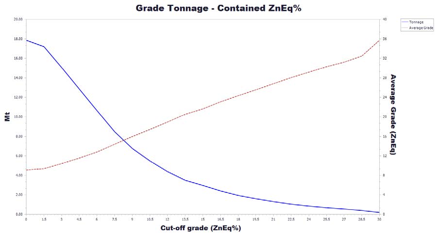
Source: SRK, 2017
Figure 14-6: Grade-Tonnage Curve for Contained ZnEq%
| 14.15 | Relevant Factors |
SRK is unaware of any environmental, permitting, legal, title, taxation or marketing factors that could limit or affect the resource stated in this document.
| 99 |
| 15 | Mineral Reserve Estimate |
There were no Mineral Reserves estimated for the Florida Canyon Project.
| 100 |
| 16 | Mining Methods |
The Florida Canyon project is located approximately 680 km north-northeast of Lima, Peru in the Shipasbamba community, Bongará Province, Amazonas Department, Peru. The approximate central point coordinates of the Project are 825,248 East and, 9,352,626 North (UTM Zone 17S, Datum WGS 84). The zone of interest is a dolomitized limestone-hosted polymetallic deposit containing known zinc, lead and silver mineralization. The topography consists of mountainous terrain with deep canyons and elevations in the immediate area of the deposit ranging from 1950 to 3310 masl.
A number of factors are considered in the selection of an appropriate mining method to exploit a mineralized zone. The factors include, but are not limited to, the geometry, depth, mineralogy, continuity of mineralization, geotechnical conditions, hydrological conditions, value of the mineral, and environmental factors. In the context of the Florida Canyon project, the following key parameters were considered in the selection of appropriate mining methods described in this study:
| · | Geometry: The structure at Florida Canyon is dominated by a N50º-60ºW trending domal anticline (or doubly plunging anticline) (SRK, 2014b). This anticlinal structure results in potential mining blocks of the manto deposits oriented along shallow dipping footwall/floors with dips ranging from 0° at the hinge to 25° near the middle to outer edges of the dome. The dip is as steep as 50° in the south of the deposit near the San Jorge exploration adit. Additionally, two steeply dipping mineralized bodies have been interpreted to exist. The first, known as San Jorge (zone F1), is located at the southern end of the deposit, and the other, known as SAM (zones 2 and 3), is located on the southwest edge of the deposit. The dip of these bodies ranges from 60° to 85° in San Jorge and 55° to 80° in the SAM body. |
| · | Higher grade manto mineralization in the anticlinal dome consists of zones between 1 m and 9 m thick mantos with barren gaps between the mantos as small as 1.5 m. Twenty mantos and two steeply dipping vein structures have been modeled and are of sufficient grade to be considered for potential mining. |
| · | Depth: the mineralized bodies outcrop in several areas and the potential mining depth reaches 550 m in the steeply dipping areas and 470 m in the shallow dipping mantos in the northern extremities of the deposit. |
| · | Mineralization: the lead-zinc mineralization is generally classified into three material types – sulfide, oxide and mixed. Oxidized mineralization tends to occur in the upper zones of the deposit near the surface with sulfide material generally occurring in deeper zones. Mixed material, ranging from Zn Oxide to Total Zn ratios of 0.2 to 0.8 occurs throughout the mineralized zone but generally overly the sulfide zones. |
| · | Continuity: the modeled mantos are fairly continuous and extend 2.1 km from the southwest to the northeast. The northern area extends laterally 1.1 km perpendicular to a SW-NE trend. The steeply dipping SAM area 600 m north to south with a thickness of 2 m to more than 30 m. The modeled San Jorge body measures 500 m north to south with thicknesses ranging from 1 m to more than 25 m. |
| · | Geotechnical: Rock quality in the Chambará 2, the primary mineralized unit, is quite good (Good to Very Good Quality – Q’ 20-40). Q’ values ranged from 4 to 40 for the geotechnical domains. Open stoping with pastefill is the preferred mining method where the mineralized zone is steeper than 45° to 50°. Flatter dipping sections of the deposit may be mined by room and pillar or drift and fill methods. |
| 101 |
| · | Hydrological: The mine is located in a high rainfall environment. Infiltration of surface water persists to approximately 50 m depth and recharges groundwater via structural pathways and interconnected karst features in dolomitized and de-dolomitized carbonate stratigraphy. The potentiometric surface has been determined by a series of piezometers. This groundwater surface follows the south-southwest flow direction of Florida Canyon and daylights at the river level in the canyon. Most of the planned mining of the flat mantos will occur above the water table. Steeper zones of mineralization, such as San Jorge and Sam will occur below the water table as will parts of the Karen Milagros mantos to the north. Local inflows may be encountered when crossing faults or intercepting karst features. |
| · | Mineral Value: the average NSR value of mineralized material contained within minable shapes, including dilution, is over US$140/t. Two concentrate products, lead and zinc, are expected to be produced with the lead concentrate containing payable amount of lead and silver. |
| · | Environmental Factors: the Project is located in the upper Amazon River Basin in a high altitude tropical jungle. The rugged topography and high annual rainfall has impacted exploration and is expected to impact any future site development and construction. The location, climate, topography and sensitivity of the surrounding environment are, and will continue to be, important considerations in the design and future operation of any producing mine at the site. |
Figure 16-1 shows an overview of the modeled Mantos, SAM vein, and San Jorge vein as well as the existing San Jorge adit.
| 102 |
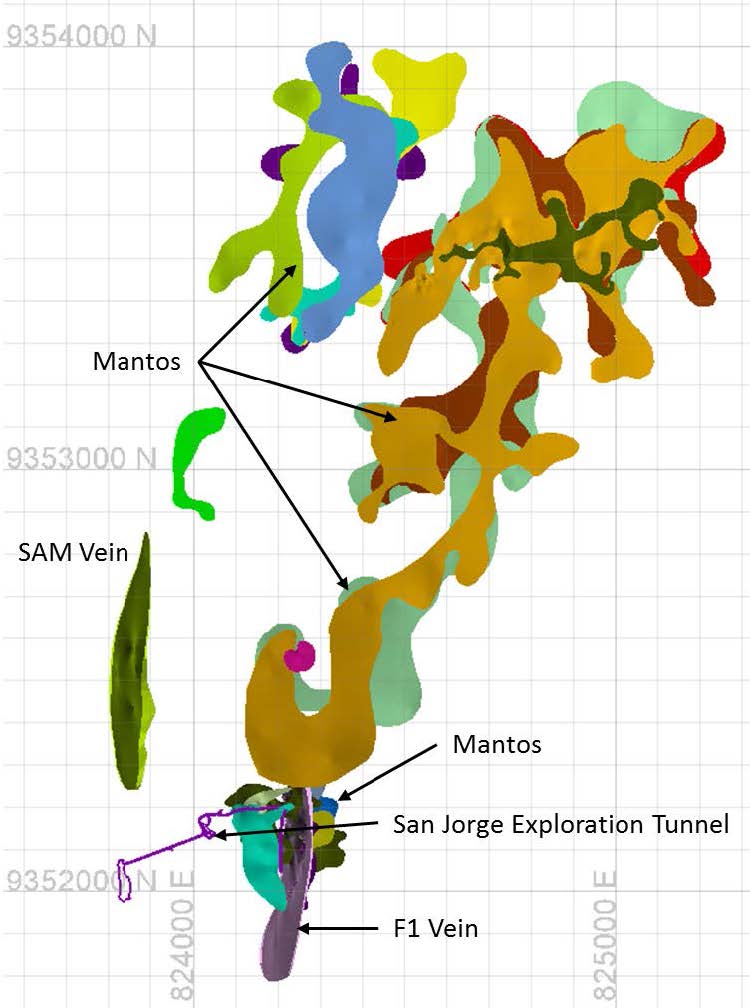
Source: SRK, 2017
Figure 16-1: Overview of Florida Canyon Mineralized Bodies
| 103 |
Figure 16-2 shows a section view of the F1 mineralized body and nearby mantos at 9,352,100N, looking north.
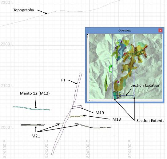
Source: SRK, 2017
Figure 16-2: Section View of the F1 Mineralized Body and Nearby Mantos (9,352,100N - Looking North)
Figure 16-3 shows a section through the SAM mineralized body and nearby mantos at 9,352,530N, looking north.
| 104 |
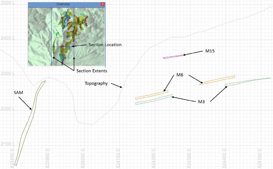
Source: SRK, 2017
Figure 16-3: Section View of the SAM Mineralized Body and Nearby Mantos (9,352,530N - Looking North)
Figure 16-4 shows a section oriented N33E through the mantos illustrating the dome structure of the mantos orebodies.
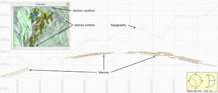
Source: SRK, 2017
Figure 16-4: Southwest to Northeast Section View Showing the Dome Structure of Mantos (Looking Northwest)
| 105 |
| 16.1 | Proposed Mining Methods |
The high-relief topography, depth and lateral extent of the mineralized zones, and environmental factors makes open pit mining of the deposit impractical. The selection of a suitable underground method or methods is required. Below is a brief generic summary of potential underground mining methods and key attributes that were considered for the application of each method.
| · | Caving techniques including block caving and sublevel caving: Typically applied to large, thick deposits with a fairly steep dip. Blocks or levels are undercut to induce caving of the block. Surface subsidence is likely. High production rates are possible. Amount of initial development is generally high. |
| · | Sublevel Stoping: Typically applied to steeply dipping veins with varying thickness. Vertical continuity is important. Top and bottom cuts (sills) are excavated above and below the stope. Parallel or fan pattern blastholes are drilled. The mineralized material is blasted in vertical slices and then mucked from the bottom sill. Stopes can be backfilled to prevent subsidence and allow mining of adjacent stopes. |
| · | Vertical Crater Retreat: Typically applied to steeply dipping, massive deposits. Similar to sublevel stoping except that blasting occurs in horizontal slices and uses large diameter blast holes. |
| · | Room and Pillar: Typically applied to flat or shallow dipping deposits. Openings are driven at regular intervals and pillars of intact rock are left behind to provide support for the openings. Recovery the mineralized material is typically lower than other mining methods due to pillars being left behind. Pillar recovery techniques can be applied to improve recovery. |
| · | Cut and Fill: Typically applied to moderate to steeply dipping deposits. Cuts are made in the mineralized material and then backfilled to provide support and allow mining of the cut above (overhand cut and fill). Mining recovery is typically high. Operating cost typically higher than unsupported or self-supported (caving, room and pillar) methods due to the cost of backfill. |
| · | Drift and Fill: Similar to cut and fill except that drift and fill is applied where the width of the mineralized material requires more than one cut on a given level. |
Other methods such as stull stoping and square set stoping have not been considered due to the high cost and generally low productivity of the methods.
Taking into account the key parameter of the Florida Canyon project, the following underground methods are suitable for application.
| · | Sublevel Stoping (Longhole Stoping) for the steeply dipping bodies identified as F1 and SAM (Figure 16-1). |
| · | Mechanized Cut and Fill for the moderate dipping bodies. |
| · | Drift and Fill for the flat to moderate dipping bodies where more than one cut is required due to the width of the zone. To increase mining recovery initial (primary) cuts are backfilled with cemented paste or rock fill and intervening secondaries are removed and backfilled with unconsolidated waste rock or paste as required. |
SRK notes that room and pillar mining has been specified in previous studies with varying mining recoveries and cut heights applied. The application of room and pillar techniques is appropriate. However, due to the relatively high grade of the mineralized material, cut and fill and drift and fill are used in the moderately dipping to flat lying zones with the goal of higher recovery of the mineralized material. Additionally, due to the topography, climate, and environmental sensitivity of the area SRK has attempted to place as much waste rock and tailings underground as possible. Conventional room and pillar mining on a checkerboard pattern could be applied to specific zones of the Florida Canyon project, particularly in lower grade areas, and should be considered in future trade-off studies at the prefeasibility level.
| 106 |
| 16.2 | Geotechnical Input for Mine Design |
The maximum thickness of the Sam and F1 mineralized zones is 12 m dipping ranging from 65° to 85°. The mineralized zones are typically 2 to 6 m wide. Open stoping with pastefill is the preferred mining method when the mineralized zone is steeper than 45° to 50°. Flatter dipping sections of the deposit may be mined by drift and fill methods as summarized in this section.
Several large (largest 25 m high x 8 m wide x 35 long) karst caverns were intersected by the exploration tunnel in a faulted area. Additional karst is observed in drilling, associated with the same normal fault plane. Karst and voids may result in difficult mining conditions and potentially delays to mining, requiring backfilling and/or additional ground support. An allowance should be made for a certain amount of non-mineable areas in karstic areas due to unfavorable ground conditions.
It is assumed for the geotechnical analysis that the ground will be depressurized by natural drainage through the mine. This is typical in karstic conditions where groundwater gradients are significant. The hydrogeology data available indicates that groundwater is structurally controlled, so local inflows may be encountered when crossing faults or intercepting karst features. It is also possible that the inflows will disappear into other karstic features downstream.
16.2.1 Geotechnical Characterization
The geotechnical characterization work for the project was performed by Klohn Crippen Berger and documented in a geotechnical report dated October 2013 (KCB, 2013a). Following is a summary of parameters developed from that study.
Within the projected underground workings, the units present are dominated by limestones and dolomites of the Chambará formation. The Chambará formation is composed of medium to dark grey limestones, dolomitic limestones and dolomites. Nodules and silicic inclusions can be found in some of these limestones. These rocks are typically massive, however karstic cavities are a common characteristic in the area. There are three main units in the Chambará formation that are characterized and influence the geomechanics of the mine design, named Chambará 1, 2 and 3, in order from earlier to later time of sediment deposition.
| · | Chambará 1 Below the mineralized zone and Chambará 2. This unit is the Footwall (FW) and will influence development of stoping areas of the mine. It is composed of sequences of fine-grain dolomites and marlstones. The units that host the mineralized body overlie the Chambará 1 units and no extraction work is expected in these zones. |
| · | Chambará 2 This is the main geotechnical domain and comprise the mineralized zone and the immediate Hangingwall (HW) and development access. It consists of dolomites and limestones. These units host the mineralized body and have an average thickness of about 200 m. The stratigraphy of Chambará 2 is geologically subdivided into 7 units, which are distinguished by the rock textural fabric and composition (packstone, wackstone, mudstone, and floatstone). |
| 107 |
| · | Chambará 3 This is above the hangingwall of the mineralized zone, and there will be development through the domain. It consists mainly of limestones of the wackestone and mudstone types. These are moderately to high bituminous limestones, and cherts can be found in some areas. Chambará 3 has an average thickness of 250 m. Fault or joint infill is typically composed of bitumen or clays. |
These geologic units are the primary Geotechnical Domains for the project.
Rock mass classifications including Rock Quality Designation, (RQD) Rock Mass Rating (RMR) (Bieniawaski, 1989) and Barton’s Q System (Q) (Barton, Lien, & Lunde 1974) for the units of interest are listed in Table 16-1. Q’ values ranged from 4 to 40 for the geotechnical domains listed. Values listed in bold are median values, and the range of values is listed in parentheses. These tests were conducted according to ISRM standards which are the industry standard. Rock quality in the Chambará 2, the primary mineralized unit, is considered quite good (Good to Very Good Quality – Q’ 20-40).
Table 16-1: Rock Mass Classification Parameters
| Group | Rock Types | RQD | RMR | Q’ |
| Chambará 1 (FW) | Dolomite and Marlstone | 80 (30-100) | 85 (61-100) | 40 (1-100) |
| Chambará 2 (mz zone) | Dolomite and Limestone | 80 (0-100) | 80 (41-100) | 20-40 (10-100) |
| Chambará 3 | Wackestone and Mudstone | 45 (0-100) | 75 (41-100) | 4 (1-30) |
Source: SRK, 2017
Intact Rock strengths, as measured by Uniaxial Compressive Strength (UCS) testing, are more than 75 to 100 MPa, based on the laboratory testing completed on Chambará 2 and 3. Figure 16-5 illustrates a histogram of the intact UCS test results. Statistical analysis of the data indicates the mean UCS is 125 MPa, with a lower bound of 100 MPa and an upper bound of 150 MPa in Chambará 2. These tests were conducted according to ASTM standards which are the industry standard. Rock strength in the Chambará 2 (mz zone) is considered quite strong.
| 108 |
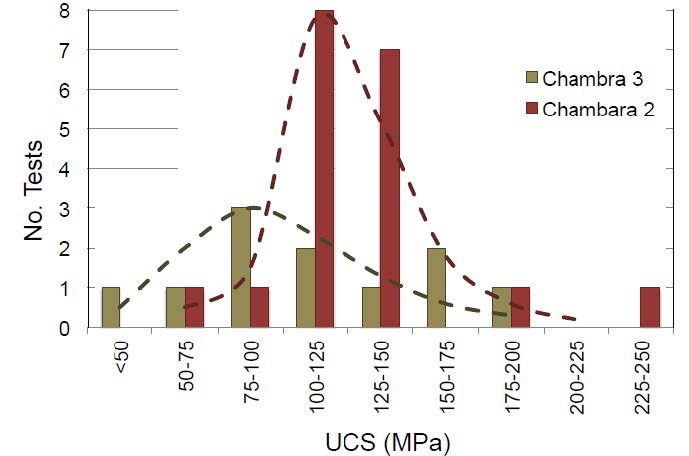
Source: KCB 2013a
Figure 16-5: UCS Strength Testing Summary
16.2.2 Stress Field and topography
No stress measurements have been made on-site. The orientation of the principal stress field is in an east to east-northeast horizontal direction estimated from the world stress map based on back-analysis of earthquake focal mechanisms at great depths. This is oriented sub-parallel to the direction of subduction that is occurring along the Andean mountain range.
Steep terrain and local faulting will result in local variations in the stress field. Maximum horizontal stresses will tend to be sub-parallel to the strike of major faults. Minimum stresses near the existing natural slope faces will tend to be aligned normal to this face. Within the mineralized body, the presence of large karstic caverns will also cause stress relief and rotation of stresses near caverns.
The vertical in situ stress (sv) magnitude is generally taken as the unit weight of the overlying rock times the depth. The average vertical stress gradient is assumed at 0.027 MPa/m.
The horizontal stress ratio (sH:sv) is not known, but in seismically active subduction regions of Peru, it is thought to be elevated above the vertical stress. The average horizontal stress ratio can be conservatively assumed as 1.2 for underground design purposes.
| 109 |
16.2.3 Cut and Fill parameters
In cut and fill areas KCB recommended 35 m stope lengths in 2.50 to 3.0 m wide and high mineralized zones. They also recommend 16 m high sill pillars every 35 m vertically. Based on SRK’s review of the available data, with good paste filling it may be possible to get three times that distance (about 100m) based on the good rock mass quality of the hangingwall rocks and tight backfilling for the PEA level design. For cut and fill paste backfill will require a minimum of 1% to 2% cement to dewater the fill and minimize the potential for liquefaction.
16.2.4 Sub-level Open Stoping Parameters
When the mineralized zone is steeper than 45° to 50° open stoping with paste backfill is the preferred mining method. The recommendations and dimensions listed are also applicable to the near vertical sections of the deposit. Rock quality in the Chambará 2 is quite good (Good to Very Good Quality – Q 20-40) which means larger stopes. Areas with flatter dips need stope stability to be managed. Chambara 2 contains the mineralized zone of the deposit. There is sufficient thickness of Chambara 2 on the order of tens of meters and is sufficient to support the hanging wall of the stoping section of the mine. Stacked manto stope areas should be mined from the top hangingwall to the footwall sequence.
Assessment of stable stope dimensions has been made using the empirical Stability Graph Method (Potvin 1988). The main objective has been to first confirm the stability of 16 m high stopes, then examine the potential for alternative dimensions.
Stability Graph Method
The Stability Graph method makes use of a stability number, N’, to derive hydraulic radius values (area
÷ perimeter) for limiting stable stope wall dimensions from a stability graph. The method is based on empirical relations from case histories and is well proven as an industry accepted method, especially at the PEA level design. As the project moves to a feasibility or design level additional stability modeling using numerical methods is recommended.
The stability number is calculated from a Q’ rating multiplied by factors A, B, and C, which take account of the stress to strength ratio in the stope wall (A), the orientation of critical joint sets relative to the stope wall (B), and the orientation of the stope wall itself (C).
N’ = Q’ x A x B x C (Equation 16.1)
An empirical chart (the Stability Graph), has been derived (Potvin, 2001) from many real stope stability cases studies from various countries worldwide, and relates N’ to hydraulic radius for cases where stope dimensions are stable, partially unstable (or would prove unstable over long time periods), or would collapse or cave. Stability limits are defined both for unsupported and supported cases, where support would comprise cable bolting.
Hydraulic radius (HR) is the ratio of the surface area to perimeter of the stope wall, from which wall dimensions can be derived.
HR = Area of open stope hanging wall surface = width x length Perimeter of hanging wall surface 2 (length + width)
It is possible to define critical hydraulic radii for stability under both unsupported and supported conditions using this method, given local geotechnical conditions and stope wall orientations. The HR is then adjusted to optimize possible stope dimensions without making dimensions so large that the stope is likely to become unstable.
| 110 |
Figure 16-6 illustrates the median and lower bound stability numbers for the wall and back. These are based on a lower bound Q value of 10 in the Chambará 2 Both the median and lower bound values plot within the unsupported transition zone, indicating that the wall and back will be stable without support. Input parameters for the stability graph are listed in Table 16-2. Chambara 3 ground conditions are poorer compared to Chambara 2, but there will is sufficient thickness of Chambara 2 above the back of the stopes, and it is the controlling geotechnical domain for the stope dimensions.
Table 16-2: Stope Stability Graph Input Parameters
| Material | Q’ | A | B | C | N’ | HR | ||
| low | med | low | median | |||||
| Chambara 2 - wall | 40 | 70 | 1 | 0.4 | 5 | 80 | 140 | 16 |
| Chambara 2 - back | 10 | 20 | 1 | 0.8 | 5 | 40 | 80 | 13 |
SRK, 2017
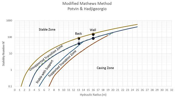
Source: SRK, 2017
Figure 16-6: Empirical Stability Graph for Stope Geometries in Chambara 2
Stability of the transverse hangingwall in 50° to 60° dipping mineralization will be the limitation on the size of the opening. KCB has recommended 300 m long transverse stopes in mantos that are 7 m high. This size stopes might be most efficiently mined with overcut and undercut with retreat mining the sill in between. The 2.5 to 3 m height is considered quite narrow such that stability of the back is not the critical factor in the design in the steeper dipping vertical sections of the mine.
The rock mass inputs to the design and resulting stope dimensions are based on median values of rock mass parameters and a resulting stability number N’. The lower bound case for the Chambara 2 rock mass has been analyzed, and the stope dimensions presented are still valid for this case. The results still plot within the limits of the unsupported transition zone. If ground conditions are worse than indicated by the drill core the transverse stope length may be shortened without affecting the overall design.
Table 16-3 lists the recommended stope dimensions for varying drift sizes. These are appropriate at a PEA level. Detailed stope sequencing and stress analysis is recommended for a feasibility level study and final mine design.
| 111 |
Table 16-3: Proposed Stope Dimensions
| Sizes w x h (m) | Mz Zone | HR |
Width (m) |
Height (m) |
Length (m) |
Area (m2) |
Perimeter (m) |
Maximum Height Allowed (m) |
| 2.5 x 2.5 | Wall | 16 | 6.5 | 300 | 1,950 | 613 | 36 | |
| Back | 13 | 2.5 | 6.5 | 16.25 | 18 | NA | ||
| 2.5 x 3.0 | Wall | 16 | 7 | 300 | 2,100 | 614 | 36 | |
| Back | 13 | 3 | 7 | 21 | 20 | NA | ||
| 3.0 x 2.5 | Wall | 16 | 6.5 | 300 | 1,950 | 613 | 36 | |
| Back | 13 | 2.5 | 6.5 | 16.25 | 18 | NA | ||
| 3.0 x 3.0 | Wall | 16 | 7 | 300 | 2,100 | 614 | 36 | |
| Back | 13 | 3 | 7 | 21 | 20 | NA |
Source: KCB (2014a)
16.2.5 Crown Pillar
The scaled span method was used to assess the stability of the crown pillar for the stopes (Carter, 2014). This analysis was conducted to prevent a collapse of mine workings to the surface. Based on this analysis, if the stope size is restricted just below the crown and near the surface, then the crown pillar could be reduced to an equivalent of two to three times the span width.
However, a minimum crown pillar of 30 m is assumed and used for this study. This is based on the steep topography at the site, and wanting to ensure that no stopes or openings approached the surface. Tight paste backfill of all stope openings is required.
Detailed analysis, including local surface topography, and calculation of crown pillar thickness should be reevaluated at a FS level study and for final stope design. An opportunity for the project is to evaluate the mineralized zone near the surface and to determine if additional material could be brought into the mine plan.
16.2.6 Sill Pillar Dimensioning
According to the analysis sill pillars will be required at 35 m intervals, laterally along dip in the shallow dipping areas (less than 45°). In the steeply dipping vertical areas sill pillars with a height of 16 m may be used for every 96 m (six levels) of vertical excavation. It is assumed that 50% of these pillar levels will be able to be recovered on retreat. This may be able to be optimized depending on the geotechnical parameters of the paste fill material used. The sill pillars left should be the width of the stope being opened, which is expected to be the height of the orebody between 2.5 to 3 m.
Partial recovery of the sill pillars may be possible. Detailed numerical modeling of the stope sequencing and a cost benefit analysis of ground support, dilution and recovery should be made. During feasibility and final design sill pillars should optimally be placed in either lower grade zones or waste if possible.
| 112 |
16.2.7 Ground Support
The ground support estimate is based on the rock mass classification and on-site experience in the exploration drift. Based on the median Q values of 20 to 40 in Chambará 1 and 2, 75% to 90% of the ground is not estimated to require ground support. Local spot bolting around faults or shear zones may still be required. The local support classification is support class 1 (lowest level) unsupported ground. It is estimated that 10% to 25% of development openings will require mesh, bolts and 50 mm of shotcrete. Some drifts and openings in Chambará 3 will require pattern bolting and mesh / shotcrete (Class 4 support).
Short-term access to stopes and cut and fill areas (less than 2 years) may use friction bolts. Long term (greater than 2 years) bolt elements should consist of fully grouted (cement or resin) bar.
The estimated ground support parameters were developed based on Barton’s tunneling quality index Q values as illustrated on Figure 16-7. Dimensions of the access drifts and input parameters for the Barton analysis are listed on Table 16-4. A ground support schedule estimate is listed on Table 16-5. This table lists the estimated percentage of ground for each ground support class and each geotechnical unit. Ground support elements for each class are detailed.
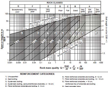
Source: Grimstad and Barton, 1993
Figure 16-7: Grimstad and Barton Ground Support Estimate
| 113 |
Table 16-4: Parameters for the Barton Method
| Excavation | Type of Excavation | Opening Dimensions W x H (m) | ESR | De |
| Min | ||||
| Access Drives | Long Term 2+ years | 5 x 5 | 3 | 1.7 m |
| Development Drives | Short to Medium Term 1-2 years | 4 x 4 | 2.5 | 1.6 m |
Source: SRK
| 114 |
SRK Consulting (U.S.), Inc.
NI 43-101 Technical Report, Preliminary Economic Assessment – Florida Canyon Zinc Project Page 116
Table 16-5: Estimated Support According to the Barton Method
| Geotechnical Zone | Amount of Expected Ground |
Q' |
Ave Q | Rock Classes |
Excavation |
Support Categories | Bolt Length | Bolt Spacing | Other support |
|
Chambara 1 & 2 |
75% - 90% |
40 + |
20 |
Good - Very Good |
Access | 1 - Spot bolting (15/10 m) | 2.5 m | ‘- | grouted bar |
| Development |
1 - Spot bolting (15/10 m) |
2.5 m | ‘- | Split sets | |||||
|
Chambara 1 & 2 |
10% - 25% |
20-40 |
4 - 20 |
Fair- Good |
Access |
4- Bolts, mesh and shotcrete |
2.5 m | 1.2 m | fully grouted bar,mesh, 4 cm shotcrete |
| Development |
4- Bolts, mesh and shotcrete |
2.5 m | 1.2 m |
fully grouted bar,mesh, 4 cm shotcrete | |||||
|
Chambara 3 |
65% - 75% |
4 + |
2 |
Fair |
Access |
1 - Spot bolting (15/10 m) |
2.5 m |
1.6 m |
grouted bar |
|
Chambara 3 |
10% - 25% |
1 - 4 |
0.2-0.7 |
Poor |
Access |
4- Bolts, mesh and shotcrete |
2.5 m |
1.2 m |
fully grouted bar,mesh, 6 cm shotcrete |
Source: SRK
| 115 |
16.2.8 Tailings Backfill
Paste-fill assume sufficient cement content to de-water the paste, so that the material will not liquefy. For stope backfill 1% to 2% cement backfill is recommended for costing.
| 16.3 | Mine Design |
The analysis provided in this report is preliminary in nature. The reader is cautioned that Mineral Resources are not Ore Reserves and have not demonstrated economic viability. There is no certainty that this preliminary economic assessment will be realized.
Twenty manto shapes and two steeply dipping vein structures have been modeled as three dimensional (3D) wireframes based on drilling and represent shapes above a 0.5% Zn cut-off. A resource block model was also used. The block model contained estimated silver, lead, and zinc values as well as estimates for the ratio of oxide to total content for each commodity (silver, lead and zinc). Each block model block has been classified so that Measured, Indicated and Inferred Mineral Resources can be identified. Blocks in the resource model measures 6 m x 6 m x 3 m in the x, y and z directions, respectively.
Potential mining blocks shapes were constructed using Maptek Vulcan’s implementation of Alford Mining System’s Stope Shape Optimizer (Stope Optimizer). Considering the size and shape of the individual mineralized bodies as well as the concepts inherent in Stope Optimizer, the resource model blocks needed to be resized to produce a more realistic representation of the potential mining block shapes. Blocks in the model were re-blocked to a minimum size of 1 m x 1 m x 0.5 m based on the wireframe shapes. The grade values of the original blocks were applied to the blocks inside the wireframe shapes. Grade values of 0 were assigned to the blocks outside the wireframes. Figure 16-8 shows an example section at 9,353,600N (looking north) comparing the original resource model blocks and the re-blocked model blocks with the M6 manto wireframe.
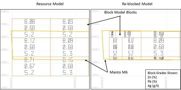
Source: SRK, 2017
Figure 16-8: Section View Showing Resource and Re-blocked Model (9,353,600N - Looking North)
| 116 |
16.3.1 Net Smelter Return
The mineralized zones at Florida Canyon are polymetallic with zinc, lead and silver contributing to the total value of mineralized material. Because the value of the mineralization is not based on one commodity, the minable inventory estimate utilizes a Net Smelter Return (NSR) cut-off approach. NSR is defined as the proceeds from the sale of mineral products after deducting off-site processing and distribution costs and is typically expressed on a dollar per tonne basis. An NSR approach is commonly used in the mining industry for polymetallic deposits and is considered best practice. Inputs into the NSR calculation include the grade of material, processing recovery, commodity prices, concentrate shipping charges, and treatment and refining charges.
Resource grades are estimated for each block in the resource block model. As described above, the resource block model has been reblocked to provide better definition around the wireframe models. Processing recoveries are modeled to be variable depending on the ratio of zinc metal associated with oxide mineralization to total zinc (ZnOx/ZnT). The expected processing recovery for each element is shown in Table 16-6.
Table 16-6: Expected Processing Recoveries
| Parameter | Alteration State | ||
| Sulfide | Mixed | Oxide | |
| ZnOx/ZnT Ratio | <= 0.2 | 0.2 to 0.8 | >= 0.8 |
| Zn Recovery | 93% | (-0.8833 (ZnOx/ZnT) + 1.1067)*100 | 40% |
| Pb Recovery | 84% | (-0.7333 (ZnOx/ZnT) + 0.9867)*100 | 40% |
| Ag Recovery | 56% | (-0.4 (ZnOx/ZnT) + 0.64)*100 | 32% |
Source: SRK, 2017
Recent work completed by Votorantim has demonstrated that oxide and mixed material with higher oxide content can be processed, though at a lower recovery, and should be included as potential mining material in the inventory. Material processed at Florida Canyon will be made up of primarily sulfide and transition material. In SRK’s opinion there is no need to exclude oxide material from consideration unless economics or further metallurgical and processing test results indicate that a specific ZnOx/ZnT cut-off should be used to restrict material input to processing.
Two concentrate products will be produced, a lead concentrate and a zinc concentrate. The lead concentrate will contain payable amount of lead and silver. No payable silver content is expected in the zinc concentrate.
As of the effective date of this report, metals pricing in US dollars is exhibiting relatively significant volatility. The spot zinc price has ranged between US$1.10/lb and US$1.33/lb over the past six months, spot lead price has ranged from US$0.89/lb to US$1.00/lb, and spot silver price has ranged from US$15.74/oz to US$18.56/oz. Long term analyst forecasts range from US$0.80/lb to US$1.38/lb, US$0.55/lb to US$0.96/lb, and US$10.94/oz to US$20.00/oz for zinc, lead and silver, respectively. For the purposes of stope optimization and defining potential mining blocks for further analysis in this study, pricing of US$1.20/lb Zn, US$1.00/lb Pb, and US$17.50/oz Ag has been used.
The parameters used in the NSR calculation for stope optimization are summarized in Table 16-7. Note that these values may vary somewhat from those used in the final economic model. An NSR value was assigned to each block model block in Vulcan software. Blocks outside the modeled wireframes, or with a zero grade, or with a classification of undefined have been assigned an NSR value of 0.
| 117 |
The mineralized bodies outcrop in several areas. Underground mining in these near-surface zones is higher risk and may not be possible given the topography and environmental conditions. A 30 m buffer below topography was created, and the blocks within this buffer zone have been assigned an NSR value of 0 so that underground stopes shapes are not produced in these areas. The quantity of Measured, Indicated or Inferred material in the resource model above the NSR cut-off and above the 30 m buffer is 151,000 t. Further study is required to determine if this material is minable using underground or surface methods.
Table 16-7: NSR Calculation Parameters for Stope Optimization
| Parameter | Unit | Value |
| Metal Prices | ||
| Zn price | US$ / lb Zn | $1.20 |
| Pb price | US$ / oz Ag | $1.00 |
| Ag price | US$ / oz Ag | $17.50 |
| Recovery to Concentrate | ||
| Zn | % | 40% to 93% |
| Pb | % | 40% to 84% |
| Ag | % | 32% to 56% |
| Concentrate Grade | ||
| Zn | % | 50% |
| Pb | % | 50% |
| Moisture Content | % | 9% |
| Transportation and Treatment/Refining Charges | ||
| Transportation Charge | US$/t concentrate | $70.00 |
| Zn treatment charge | US$/t concentrate | $115.00 |
| Pb treatment charge | US$/t concentrate | $100.00 |
| Zn refining charge | US$/lb Zn | $0.115 |
| Pb refining charge | US$/lb Pb | $0.100 |
Source: SRK, 2017
| 118 |
An example NSR calculation for an individual block is shown in Table 16-8.
Table 16-8: Example NSR Calculation
| Parameter | Units | Value |
| Volume | m3 | 7.5 |
| Density | t/m3 | 2.89 |
| Tonnage | t | 21.7 |
| Resource Zn | % | 6.62 |
| Resource Pb | % | 0.05 |
| Resource Ag | g/t | 9.78 |
| Contained Zn | lb | 3163.4 |
| Contained Pb | lb | 23.89 |
| Contained Ag | oz | 6.82 |
| Zn Recovery | 0.93 | |
| Pb Recovery | 0.84 | |
| Ag Recovery | 0.56 | |
| Recovered Zn | lb | 2941.9 |
| Recovered Pb | lb | 20.06 |
| Recovered Ag | oz | 3.82 |
| Value Zn | US$ | $3530.33 |
| Value Pb | US$ | $20.06 |
| Value Ag | US$ | $66.79 |
| Zn Concentrate (wet) | t | 2.91 |
| Zn Concentrate (dry) | t | 2.67 |
| Pb Concentrate (wet) | t | 0.20 |
| Pb Concentrate (dry) | t | 0.18 |
| Zn Concentrate Shipping | US$ | $203.60 |
| Zn Concentrate Treatment/Refining | US$ | $645.25 |
| Pb Concentrate Shipping | US$ | $1.40 |
| Pb Concentrate Treatment/Refining | US$ | $3.83 |
| Net Block Value | US$ | $2,763.09 |
| NSR | US$/t | $127.48 |
Source: SRK, 2017
16.3.2 Operating Costs
A number of technical studies have been completed on the project by both internal teams and external consultants. The production rate in these studies has ranged from 2,000 to 4,000 t/d. Considering the previous work and the geometry and size of the mineralized zones as they are currently known, a 2,500 t/d production rate has been selected. Operating costs used in the determination of potential mining shapes are based on previous studies of the Florida Canyon project, estimating manuals, first principals, and comparing the Florida Canyon project with similar operations in Central and South America. Table 16-9 lists the operating costs used to determine potential mining shapes for Florida Canyon.
| 119 |
Table 16-9: Operating Costs Used for Determining Potential Mining Shapes
|
Item |
Cost (US$/t) Longhole | Cost (US$/t) Drift and Fill/ Cut and Fill |
| Mining | 24.40 | 25.93 |
| Processing | 12.00 | 12.00 |
| G&A | 5.00 | 5.00 |
| Total | $41.40 | $42.93 |
Source: SRK, 2017
16.3.3 Stope Optimization
Potential mining blocks shapes were constructed using Maptek Vulcan’s implementation of Alford Mining System’s Stope Shape Optimizer (Stope Optimizer). NSR values were calculated using the parameters described in Section 16.3.1 for material classified as Measured, Indicated or Inferred. All other blocks are assumed to be waste with NSR and grade values of zero.
The mining method applicable to the San Jorge and SAM mineralized bodies is longhole stoping. Nominal level spacing in the longhole areas is 16 m from sill to sill. Potential mining shapes were allowed to have a minimum width of 3 m. Mining in these narrow areas would likely utilizing a resue mining technique to control dilution, and upon inspection of the resulting shapes there were few stopes at the minimum width in F1 and SAM. Both longitudinal stopes (stopes oriented along strike) and transverse stopes (oriented perpendicular to strike) exist in the mining zones.
The mining methods applicable to the flat to moderate dipping areas is drift and fill and cut and fill. A minimum cut height of 3 m has been used with the potential mining blocks are oriented horizontally. SRK notes that in practice the mining cuts in the flat to shallow dipping areas will likely follow the footwall. That level of detailed design, however, is beyond the scope of this study and should be undertaken in subsequent PFS level study.
Key parameters used for stope optimization are provided in Table 16-10.
Table 16-10: Stope Optimization Parameters for Base Case Analysis
| Mining Method | Longhole | Drift and Fill/ Cut and Fill |
| Minimum Stope Width (m) | 3 | 3 |
| Minimum Waste Pillar Width (m) | 3 | 3 |
| Stope Height (m) | 16 | 3 |
| Cut-off (NSR) | US$41.40 | US$42.93 |
Source: SRK, 2017
The stope blocks output from Stope Shape Optimizer were visually inspected. Isolated blocks; i.e., small blocks far from larger groups of blocks or where additional development is not practical or economically feasible, were identified for removal from the mining block inventory. A small number of blocks were also removed in manto areas near the F1 longhole blocks. The blocks were removed due to the likelihood that mining induced stresses from exploitation of the nearby manto blocks would introduce stability issues in F1 zone. Figure 16-9 shows an example level section at 2044.5 elevation in the F1 area. Blocks flagged for removal are outlined in red. Approximately 273,000 t of material was removed from the inventory over the entire Florida Canyon project area and is less than 2.5% of the tonnes within the inventory.
| 120 |
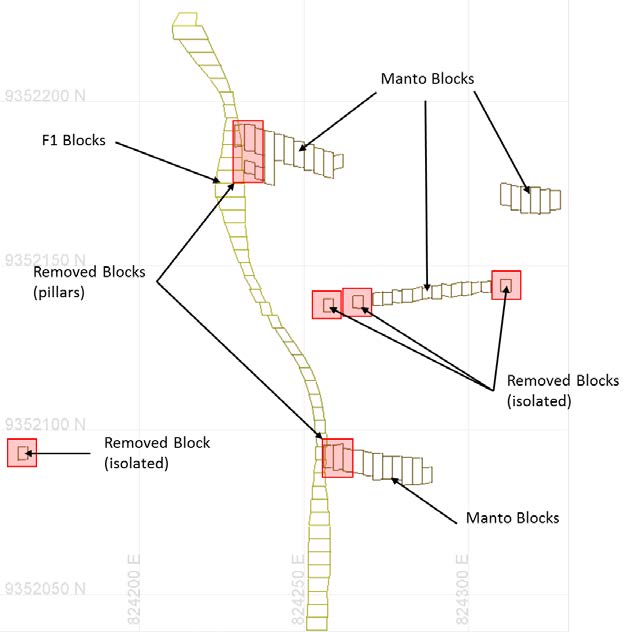
Source: SRK, 2017
Figure 16-9: Section View Showing Blocks Removed from Inventory
The resource model was queried against the final stope optimization shapes to determine tonnes and grade of material inside the shapes, and mining dilution and recovery factors were applied in a spreadsheet.
16.3.4 Mining Recovery and Dilution
The undiluted tonnes and grade of each potential mining block is based on the resource block model. Minable inventory tonnes and grade are calculated using the following factors:
| · | Mining Recovery: a factor resulting in material loss (tonnage reduction) due to the mining method applied and the deposit geometry; and |
| · | Dilution: a factor resulting in a reduction of the overall average grade due to the mining of waste with the mineralized material. |
The generalized formula for calculating the reserve tonnage in each mining block is: Tinventory = Tmining block * Mining Recovery% * (1+Dilution%unplanned)
The generalized formula for calculating the reserve grade is: Ginventory = Resource Grademining block / (1+Dilution%unplanned)
| 121 |
Recovery of 100% of the mineralized material within a mine design is rarely, if ever, achieved. Loss of mineralized material can be the result of:
| · | Underbreak – the mineralized material is not blasted loose and remains in the stope walls; |
| · | Mineralized material loss within stope – the blasted mineralized material is left in the stope due to poor access for the loader, buried by falls of waste rock from walls, left on the floor, or material blasted but does not fall from flatter lying walls; and |
| · | Mineralized material left in pillars – loss due to leaving material behind to provide ground support. |
The mining recovery applied to the areas using the longhole method is 90%. Pillars with a height of 16 m have been planned for every 96 m (six levels) of vertical excavation. It is assumed that 50% of these pillar levels will be able to be recovered on retreat. The mining recovery applied in the drift and fill and cut and fill areas is 95%.
Dilution is defined as the ratio of waste to mineralized material above cut-off. There are two types of dilution that would be expected in the mine: internal, also called planned dilution; and external, also called unplanned dilution.
| · | Internal or planned dilution occurs when material less than a cut-off grade falls within a designed stope boundary (i.e., it would be drilled and blasted within the stope during mining). |
Internal dilution is incorporated into the design when constructing shapes encompassing the material above cut-off. If the average grade of the stope falls too low when this material is incorporated into the stope, the stope should be redesigned to exclude more of this low-grade material. Judgment must be exercised during the stope optimization and/or design process to minimize dilution from this source, but practical mining considerations usually make the inclusion of internal dilution unavoidable. Internal dilution is straightforward to quantify in a mine plan using software to calculate tonnes and grade above and below the Net Smelter Return (NSR) cut-off within the designed stope blocks.
| · | External or unplanned dilution is derived from low- or zero-grade material outside the stope design boundaries. This dilution is the result of over-break arising from poor drilling and blasting techniques, adverse geological structures, and failure within zones of weak rock. |
No additional external dilution has been applied to the Florida Canyon mining shapes. Internal dilution for the base case Florida Canyon scenario ranges from 13% to 73% and averages 34%. It is expected that a detailed design would likely reduce the overall average dilution. A detailed design, however, is beyond the scope of this study.
16.3.5 Cut-off Evaluation
The NSR value of each potential mining block was calculated and evaluated against the NSR cut-off value for the particular mining method to be applied to the block. The NSR cut-off includes mining costs, processing costs, and general and administrative costs as described in Section 16.3.2. Mining blocks with an average NSR value above the NSR cut-off are included in the minable inventory. In some cases, marginal blocks, defined as blocks below the economic cut-off but above the sum of the cost of mining and processing, are included in the inventory if they are adjacent to economic blocks and it is reasonable to expect that no significant additional development would be required to extract the marginal block. Mining blocks not meeting the criteria described above are classified as waste and excluded from the inventory.
| 122 |
16.3.6 Mining Methods
Approximately 26% of the mining resource will be mined using longhole stoping in the SAM and F1 areas with the remaining mined using mechanized drift and fill and cut and fill. Cemented paste fill and cemented rock fill will be used to backfill primary stopes. Mine development waste will be used in secondary stopes with some secondaries backfilled with low-content cemented paste fill where required.
Longhole Stoping
Sublevels in the longhole areas will be developed at 16 m intervals. Stopes less than 8 m wide will be mined longitudinally (along strike) with stopes greater than 8 m wide mined transversely (perpendicular to strike). Ramp, main haulage, and cross-cut development will be in the footwall. Haulage drifts have been offset from the stopes by 20 m. Sill development in the mineralized zones will provide access for drilling, blasting, ground support, and mucking. Blasthole drilling will be from the top sill using top hammer drills. Broken material will be mucked from the bottom of the stopes using remote controlled Load Haul Dump units (LHD). Typical blast patterns will be drilled using 2.5 m (burden) x 2.0 m (spacing) ring patterns. It is expected that water will be present requiring blastholes to be charged with ANFO/emulsion blends as required for water resistance. Cut and fill mining blocks exist in the hangingwall and footwall in the F1 area. Consideration for good ground control and the influence of mining induced stresses has an impact on the sequence of mining in these areas. The production schedule described in this study has mining occurring from the hangingwall to footwall with cut and fill blocks in the footwall mined on retreat. Figure 16-10 shows the F1 area and the proximity of cut and fill blocks to longhole blocks. Figure 16-11 shows a typical longhole level layout.
| 123 |
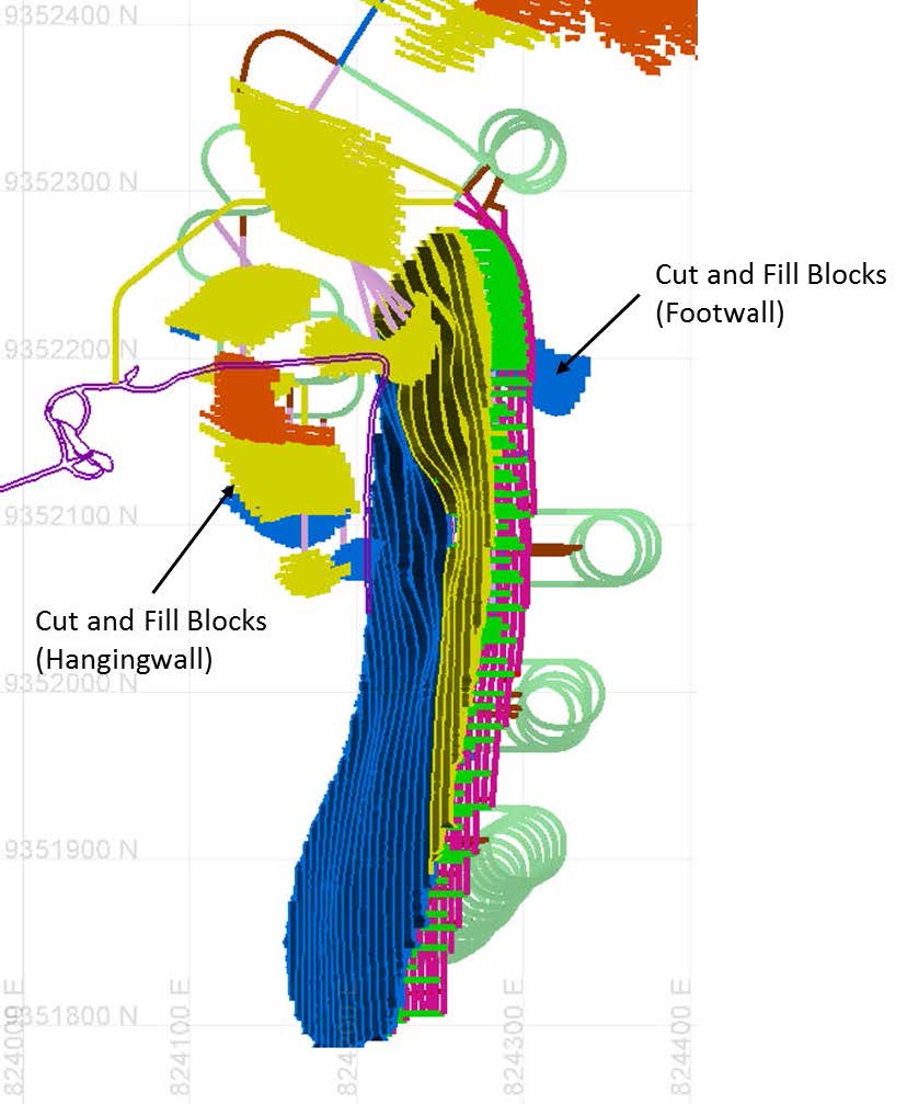
Source: SRK, 2017
Figure 16-10: Plan View of F1 Area Showing Cut and Fill and Longhole Blocks
| 124 |
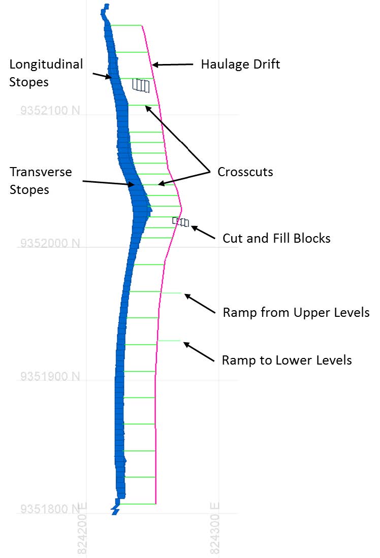
Source: SRK, 2017
Figure 16-11: Section View Showing Typical Longhole Level Layout (Elevation 1981)
Drift and Fill, Cut and Fill
Mining of shallow dipping (less than 27°) accounts for 70% of mine production. Mining cuts measuring 4 m wide x a minimum 3 m high will be used to minimize dilution in thin areas. Stopes within a given manto or group of mantos will be developed from the bottom-up with each subsequent 3 m level developed above the mined-out and backfilled cut below. It will be possible to develop ramps and haulage drifts in the mineralized material where the dip of the mineralized zone allows a maximum 12% gradient. Stopes will also be able to follow the grade of the footwall up to a maximum allowable gradient of 15%. An example drift and fill layout in the M10 manto is shown in Figure 16-12 with haulage access progression labeled. Drill jumbos will be used to drill 45 mm holes with each round advancing 4 m. Blasting will primarily use ANFO/emulsion blends will be used as required.
| 125 |
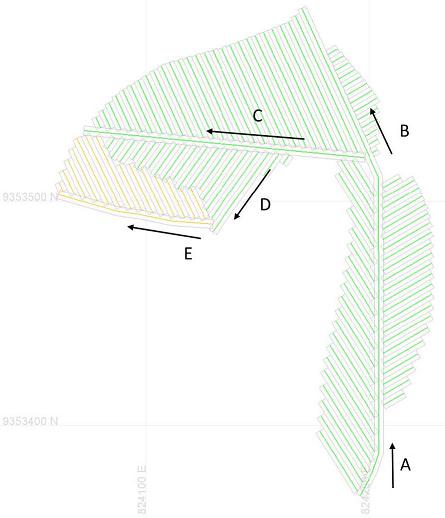
Source: SRK, 2017
Figure 16-12: Example Drift and Fill Layout, M10 Manto
Areas that require footwall waste development for stope block access will utilize access ramps with a maximum grade of 15%. Blocks of 12 to 16 m high will be mined using cuts of 3 to 4 m depending on the geometry of the mineralized material. Mining of cuts within a stope block will progress from the bottom to the top with lower cuts filled with cemented paste fill, cemented rock fill or development waste.
Large karst caverns have been encountered during the excavation of the San Jorge adit, and karstic features have been observed in drilling. Additional geotechnical and hydrogeological information and study is required to better understand the potential impact on mining and risk mitigation measures that may be required to ensure a safe working environment.
Mineralized material will be mucked using LHDs (4.5 to 6.5 m3), loaded onto 30 tonne trucks and hauled to the appropriate portal. The material will be crushed at the portal and transported to the processing facility via conveyor.
| 126 |
16.3.7 Mine Plan Resource
The tonnes and grade of the resource material contained within the mining blocks, adjusted by recovery and dilution, and categorized by the resource classification is provided in Table 16-11. The mine plan resource consists of a total of 11.2 Mt with an average grade of 8.34% Zn, 0.90% Pb, and
11.3 g/t Ag. and is made up of Measured, Indicated, and Inferred material. Estimated average dilution, processing recoveries and the ZnOx/ZnT ratio is also provided. Average process recovery and dilution for the mine plan resource are shown in Table 16-12.
Table 16-11: Mine Plan Resource for the Florida Canyon Zn-Pb-Ag Deposit, Amazonas Department, Peru, SRK Consulting (U.S.), Inc., July 21, 2017
|
Category |
Mass (kt) |
Zn Grade (%) |
Pb Grade (%) |
Ag Grade (g/t) |
NSR * (US$/t) |
ZnEq ** (%) |
Zn Contained (kt) |
Pb Contained (kt) |
Ag Contained (kg) |
ZnEq ** Contained (kt) |
| Measured | 1,293 | 10.64 | 1.33 | 15.60 | 197.12 | 12.38 | 138 | 17 | 20,157 | 160 |
| Indicated | 2,011 | 8.77 | 1.08 | 13.44 | 166.85 | 10.22 | 176 | 22 | 27,026 | 206 |
| M&I | 3,303 | 9.51 | 1.18 | 14.28 | 178.69 | 11.05 | 314 | 39 | 47,182 | 365 |
| Inferred | 7,883 | 7.86 | 0.78 | 10.07 | 135.36 | 9.03 | 619 | 62 | 79,354 | 712 |
| Total Mine Design |
11,18 7 |
8.34 |
0.90 |
11.31 |
148.16 |
9.66 |
933 |
101 |
126,536 |
1,081 |
Source: SRK, 2017
* NSR is calucalted using variable recoveries based on sulfide/oxide ratios (recovery ranging from 32%-93%), a Zn price of US$1.20/lb, a Pb price of US$1.00/lb, an Ag price of US$17.50/oz. The transportation charge is US$70.00/t conc, Zn treatment charge of US$115/t conc, Pb treatment charge of US$100/t conc, Zn refining charge of US$0.115/lb Zn, and Pb refining charge of US$0.1/lb Pb. These factors were used for mine planning and vary somewhat from the final economic model.
** ZnEq estimate is based on a NSR value of US$19.62 per 1% Zn. The US$19.62 is calculated using a Zn price of US$1.20/lb, a Pb price of US$1.00/lb, an Ag price of US$17.50/oz. The ZnEq also includes TC/RC and transportation costs and assumes an average Zn recovery of 78.15% which differs somewhat from that presented in the economic model. An example of the NSR to ZnEq calculation is (148.16/19.62)/0.7815
Table 16-12: Mine Plan Resource Average Process Recovery
| Process Recovery | ZnOx/ZnT Ratio | Dilution | |||
| Ag (%) | Pb (%) | Zn (%) | |||
| Mine Plan Resource | 51.7 | 74.3 | 79.8 | 0.26 | 34% |
The PEA is preliminary in nature, that it includes Inferred Mineral Resources that are considered too speculative geologically to have the economic considerations applied to them that would enable them to be categorized as Mineral Reserves, and there is no certainty that the PEA will be realized. Mineral Resources that are not Mineral Reserves do not have demonstrated economic viability.
Figure 16-13 shows an overview of blocks included in the final mineral inventory as well as the existing San Jorge adit.
| 127 |
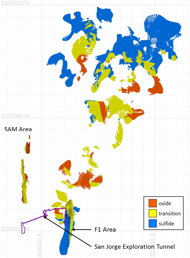
Source: SRK, 2017
Figure 16-13: Florida Canyon Mining Inventory
16.3.8 Development Layout
A development layout was created to provide access to the mining levels and to tie levels into ramps. Access to the underground workings will be via three main portals (San Jorge, P01 and P03). An additional portal (P02) will be used primarily for ventilation, and three additional drifts will daylight to facilitate ventilation. The only underground excavation that currently exists at the site is the San Jorge exploration adit. This adit will be utilized for access to the F1 area and surrounding cuts in the mantos. Dimensions of the San Jorge adit are currently 2.5 m x 3.5 m. This adit will need to be enlarged and ground support installed in the preproduction phase of the project. Production blocks in the central part of the project allow for the connection of the southern and northern areas via underground drifts and ramps. This underground connection will improve ventilation, will make the movement of personnel and equipment more efficient, and will allow for more flexibility in the production plan.
| 128 |
It is expected that development in the flat and shallow dipping mineralized zones will follow the footwall where the gradient of the drift can be less than 12%. Waste development in those areas will be limited to the primary access to the mining blocks and small connector drifts between larger blocks; for this study, only the primary access has been designed in these flat and shallow dipping areas. A more detailed level and ramp design was created for the more steeply dipping mantos, F1 and SAM areas. Cross-cuts are spaced 8 m apart on a level in transverse longhole stope areas, and 20 m cross-cut spacing is used in the transverse areas. Attack ramps in the mantos where development of ramps within the mineralization are typically 55 m or less and have a maximum gradient of 15%.
The mine design assumptions are listed in Table 16-12.
Table 16-13: Development Design Assumptions
| Parameter | Value |
| Maximum Ramp Gradient (Primary Ramps) | 12% |
| Maximum Gradient (Stope Access, Attack Ramps) | 15% |
| Primary Development Dimensions (w x h) | 4 m x 5 m |
| Secondary Development Dimensions (w x h) | 4 m x 4 m |
| Primary Ventilation Raise (diameter) | 4 m |
| Ventilation Raise Between Levels (diameter) | 3 m |
| Ore Pass (diameter) | 2 m |
Source: SRK, 2017
An additional development allowance of 10% has been applied to the primary ramp, main haulage and level access drifts to account for turnouts, laydowns, and miscellaneous ventilation and ore pass development that will be required but was not designed in detail on each level. It is expected that raise boring will be contracted. Development quantities are presented in Table 16-13.
Development has been classified as capital and operating. Capital waste development makes up the mine’s long term and permanent infrastructure and includes primary ramps, level accesses, main haulage levels, ore passes, and ventilation raises. Operating waste development includes stope accesses and crosscuts. Three ventilation raises to surface are designed to ensure proper ventilation of four primary zones and the relatively large lateral extent of the project.
Table 16-14: Development Quantities
| Category | Development Drifting (Meters) |
| Lateral Development (Capital) | 30,944 |
| Ventilation Raise to Surface (Capital) | 617 |
| Ventilation Raise and Ore Passes Between Levels (Capital) | 1,078 |
| Total Capital Development Meters | 32,639 |
| Operating | 23,504 |
| Total Development Meters | 56,143 |
Source: SRK, 2017
The following figures show the development layout:
| · | Figure 16-14 shows a plan view of the mining block inventory and development layout; |
| · | Figure 16-15 shows a rotated view of the layout looking northeast; |
| · | Figure 16-16 shows a rotated view of the layout looking northwest; |
| · | Figure 16-17 shows a rotated view of the layout in the northern area of the project (drift and fill/cut and fill) looking northeast; and |
| · | Figure 16-18 shows a rotated view of the layout in F1 and SAM looking northwest. |
| 129 |
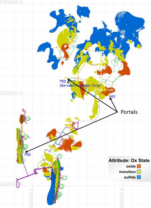
Source: SRK, 2017
Figure 16-14: Plan View of Mining Blocks and Development Layout
| 130 |
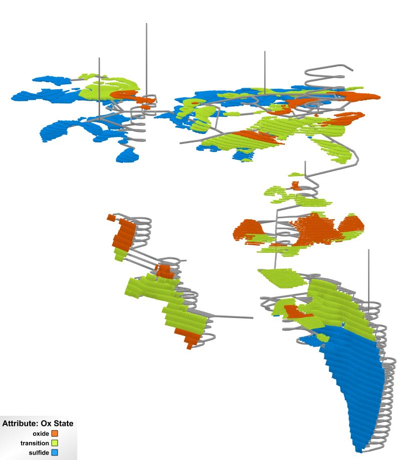
Source: SRK, 2017
Figure 16-15: Rotated View of Mining Blocks and Development Layout – All Areas (Looking Northeast)
| 131 |
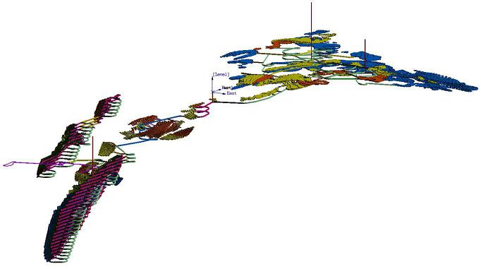
Source: SRK, 2017
Figure 16-16: Rotated View of Mining Blocks and Development Layout – All Areas (Looking Northwest)
| 132 |
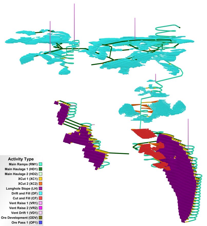
Source: SRK, 2017
Figure 16-17: Rotated View of Mining Blocks and Development Layout – Drift and Fill/Cut and Fill (Looking Northeast)
| 133 |
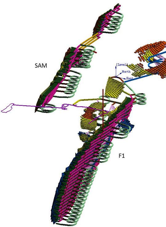
Source: SRK, 2017
Figure 16-18: Rotated View of Mining Blocks and Development Layout – F1 and SAM (Looking Northwest)
| 134 |
16.3.9 Waste Rock Management and Backfilling
Development waste excavated during the two-year pre-production period will be hauled to surface and used as construction materials; e.g., construction of the TSF embankment. This will allow stope mining to progress to a point where development waste can be placed underground. Additional development waste can be hauled to surface for construction materials where it is necessary and more cost effective than sourcing material on surface. Waste material has not been categorized in terms of its acid generating potential. It will be important in future studies to determine whether the waste material is potentially acid generating (PAG) and design storage or specify appropriate mitigation techniques should PAG material be encountered.
Backfilling is an important part of the mine plan. Backfilling stopes provides for ground support, a working platform during mining, storage for tailings, and storage of waste rock with an associated shorter haul compared to storage on surface. A mix of material will be used to backfill stopes including cemented paste tailings, cemented rockfill, and RoM development waste. The cement content will vary based on the type of waste and where it will be placed.
| · | Primary paste fill cement content: 6% by weight; |
| · | Primary rock fill cement content: 4% by weight; and |
| · | Secondary paste fill cement content (to prevent liquefaction): 2% by weight. |
It is assumed that 50% of the stopes are primaries and 50% are secondaries. The life-of-mine (LoM) backfill and cement quantities by type is shown in Table 16-15.
Table 16-15: LoM Backfill and Cement Quantities by Type
| Parameter |
Qty Fill (m3) |
Qty Cement Used (dmt *) |
| Primary cemented rock fill | 161,424 | 10,957 |
| Primary cemented paste fill | 1,700,164 | 214,221 |
| Secondary un-cemented rock fill | 1,861,588 | 0 |
| Secondary cemented paste fill | 508,479 | 4,843 |
| Total | 4,231,655 | 230,021 |
Source: SRK, 2017
* dry metric tonne (dmt)
The total tailings sent to the TSF (i.e., Process tailing less tailing required for backfill) is 4,092,844 m3, based on an average dry density of 1.6 t/m3.
| 16.4 | Mine Production Schedule |
A production rate of 2,500 t/d has been selected to mine 912,500 mineralized tonnes per year. The mine will utilize two 12-hour shifts and operate 365 days per year. A two-year pre-production period is planned where mine development efforts will include enlarging of the San Jorge adit, development in the F1 area, and development in the north of the project area. Production will ramp up in schedule year 3 (production year 1) with an average daily mineralized material production rate of 2,005 t/d. Longhole, cut and fill, and drift and fill mining occur simultaneously. Longhole mining has been planned at a rate of 1,000 t/d and drift and fill/cut and fill mining will range from 1,500 to 2,500 t/d. Full production occurs in schedule years four through 14 (11 years of full production) with mining finished late in schedule year 15. Table 16-15 shows the Florida Canyon production schedule. It is illustrated in Figure 16-19. SRK notes that there are likely opportunities to optimize the production schedule. Opportunities include improved sequencing of high grade material and, potentially, a decrease in the pre-production timeframe. A more detailed design and schedule with corresponding trade-off studies, as well as more detailed construction timeframe estimates, would be required for the next phase of study.
| 135 |
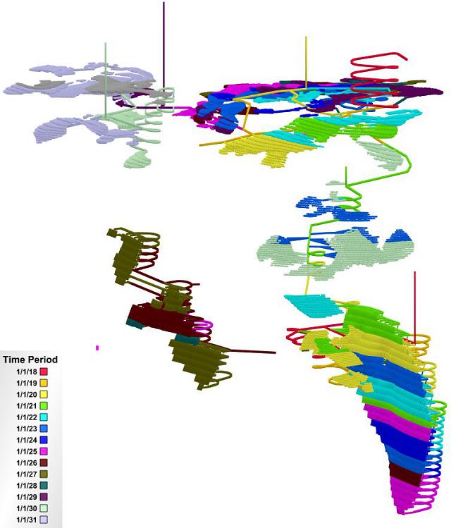
Source: SRK, 2017
Figure 16-19: Rotated View of Mining Blocks Showing Production Schedule
| 136 |
SRK Consulting (U.S.), Inc.
NI 43-101 Technical Report, Preliminary Economic Assessment – Florida Canyon Zinc Project Page 138
Table 16-16: Florida Canyon Production Schedule
| Parameter | Units | Period | |||||||
| Schedule Year Production Year | yr yr |
1 -2 |
2 -1 |
3 1 |
4 2 |
5 3 |
6 4 |
7 5 |
8 6 |
| Mineralized t/d | t/d | - | - | 2,005 | 2,498 | 2,500 | 2,502 | 2,503 | 2,505 |
| Waste t/d | t/d | 437 | 504 | 729 | 905 | 819 | 753 | 481 | 660 |
| Total t/d | t/d | 437 | 504 | 2,734 | 3,403 | 3,320 | 3,255 | 2,984 | 3,165 |
| Ag | g/t | - | - | 12.2 | 10.1 | 17.7 | 17.4 | 15.5 | 15.4 |
| Pb | % | - | - | 0.85 | 0.97 | 1.12 | 1.22 | 1.00 | 1.03 |
| Zn | % | - | - | 9.15 | 10.21 | 12.24 | 10.25 | 11.65 | 10.90 |
| ZnOx/ZnT Ratio | - | - | 0.42 | 0.52 | 0.24 | 0.16 | 0.09 | 0.07 | |
| Mineralized Tonnes | t | - | - | 733,813 | 911,858 | 912,584 | 913,222 | 915,955 | 914,271 |
| Waste Tonnes | t | 159,597 | 183,798 | 266,986 | 330,158 | 299,096 | 274,792 | 176,144 | 240,886 |
| Total Tonnes | t | 159,597 | 183,798 | 1,000,799 | 1,242,017 | 1,211,679 | 1,188,014 | 1,092,099 | 1,155,157 |
| LH Tonnes | t | - | - | 294,548 | 365,000 | 365,000 | 365,000 | 366,000 | 365,000 |
| Drift and Fill Tonnes | t | - | - | 277,995 | 514,621 | 480,998 | 534,828 | 549,955 | 549,271 |
| Cut and Fill Tonnes | t | - | - | 161,270 | 32,237 | 66,586 | 13,394 | - | - |
| Capital Dev Length (excl. Vnt. raise to surface) | m | 2,545 | 3,133 | 2,517 | 4,256 | 3,278 | 2,283 | 1,532 | 2,855 |
| Vent Raise to Surface | m | 181 | - | 131 | 42 | 8 | - | - | - |
| Opex Dev Length | m | 272 | 198 | 2,773 | 2,181 | 2,602 | 3,408 | 2,097 | 1,999 |
| Parameter | Units | Period | Totals | ||||||
| Schedule Year | yr | 9 | 10 | 11 | 12 | 13 | 14 | 15 | |
| Production Year | yr | 7 | 8 | 9 | 10 | 11 | 12 | 13 | |
| Mineralized t/d | t/d | 2,501 | 2,503 | 2,507 | 2,503 | 2,508 | 2,500 | 1,093 | 2,076 |
| Waste t/d | t/d | 965 | 880 | 40 | 97 | 339 | 135 | - | 525 |
| Total t/d | t/d | 3,466 | 3,383 | 2,547 | 2,600 | 2,847 | 2,635 | 1,093 | 2,601 |
| Ag | g/t | 9.9 | 8.9 | 6.4 | 8.3 | 7.0 | 9.3 | 6.4 | 11.3 |
| Pb | % | 1.11 | 0.90 | 0.77 | 0.98 | 0.40 | 0.56 | 0.69 | 0.90 |
| Zn | % | 8.53 | 6.39 | 4.94 | 6.43 | 5.65 | 5.40 | 5.08 | 8.34 |
| ZnOx/ZnT Ratio | 0.13 | 0.42 | 0.13 | 0.43 | 0.45 | 0.20 | 0.47 | 0.26 | |
| Mineralized Tonnes | t | 912,955 | 913,419 | 917,431 | 913,524 | 915,319 | 912,402 | 399,948 | 11,186,701 |
| Waste Tonnes | t | 352,067 | 321,253 | 14,802 | 35,532 | 123,862 | 49,225 | - | 2,828,197 |
| Total Tonnes | t | 1,265,022 | 1,234,671 | 932,233 | 949,056 | 1,039,181 | 961,627 | 399,948 | 14,014,897 |
| LH Tonnes | t | 334,680 | 358,729 | 82,538 | - | - | - | - | 2,896,495 |
| Drift and Fill Tonnes | t | 496,400 | 477,383 | 834,893 | 913,524 | 915,319 | 912,402 | 399,948 | 7,857,537 |
| Cut and Fill Tonnes | t | 81,875 | 77,307 | - | - | - | - | - | 432,669 |
| Capital Dev Length (excl. Vnt. raise to surface) | m | 3,278 | 3,174 | 118 | 475 | 1,718 | 861 | - | 32,022 |
| Vent Raise to Surface | m | - | - | - | 255 | - | - | - | 617 |
| Opex Dev Length | m | 3,847 | 3,382 | 184 | - | 482 | 78 | - | 23,504 |
Source: SRK, 2017
| 137 |
| 16.5 | Mine Services |
16.5.1 Underground Mine Equipment
Mine equipment selection is based on the mining methods employed, production requirements, expected number of open faces required to meet production, and development and stope dimensions. Double boom jumbos will be used for lateral development and single boom, low profile jumbos have been specified for drift and fill areas with cut heights of 3 m. LHDs with remote operating capabilities will be used for stope and development mucking and will load 30 t trucks. Table 16-16 provides a summary of the mining equipment.
Table 16-17: Mine Equipment
| Equipment | Example | Number |
| LH Stope DTH Drills | Atlas Copco Simba Series | 2 |
| LH Production LHD (6 m3) | Sandvik LH514 | 3 |
| Production Jumbo (D&F/C&F) | Low Profile, Atlas Copco M1L | 6 |
| D&F/C&F Production LHD (4 m3) | Sandvik LH410 | 6 |
| Horizontal Development Jumbos (2 boom) | Atlas Copco Boomer (2 boom) | 4 |
| Development LHD (6 m3) | Sandvik LH514 | 4 |
| Haul Trucks (30 t) | Sandvik TH430 | 6 |
| Rock Bolter | Atlas Copco Boltec Series | 2 |
| Anfo Loader | 2 | |
| Miscellaneous/Service Vehicles | 5 | |
| Light Vehicles/General | 5 |
Source: SRK, 2017
16.5.2 Electrical
The underground mine will be supplied by power from the main Project substation. The main underground power will be used for the crushers located at the portals, jumbos, drills, ventilation, and electric pumps. Additionally, power will support auxiliary use in the shops and for smaller loads such as secondary fans, temporary pumps, and auxiliary lighting.
16.5.3 Ventilation
A conceptual ventilation layout has been developed for this PEA study in order to estimate the number and location of ventilation openings to surface and to develop a cost estimate for ventilation. Additional detailed ventilation design is required in the next phase of study.
Ventilation of the Florida Canyon project will be subdivided into four zones. The San Jorge adit and a raise to surface will be used to ventilate the southern sections, the F1 area, of the mine. Workings in the central and northern parts of the mine, the flat to moderate dipping mantos, will utilize the newly excavated decline, a ventilation portal, and two raises to surface. The SAM area is largely isolated from the rest of the network and will be ventilated via its portals and ventilation drifts that daylight on surface. The northwestern part of the mine will be ventilated via a raise and ventilation drift daylighting on the surface.
| 138 |
Based on the equipment list SRK estimated airflow requirements using some general assumptions of average power and utilization. The airflow requirement is based on 125 cfm per brake horsepower (bhp) which is a commonly used rule-of-thumb value for this type of preliminary estimate. The number of personnel underground were estimated and airflow calculates used 55 cfm/person. A utilization percentage for equipment has not been used for airflow calculations and would reduce the required airflow. The estimated airflow requirement by zone are shown in Table 16-17 through Table 16-19 at typical production in the given zone.
Table 16-18: Estimated Airflow Requirements – Central/North and Northwest Areas
| Description | Quantity | Estimate SRK (hp) | Utilization (%) | Air Required (cfm) |
| Scoops/LHD (4 m3) | 4 | 300 | 100% | 150,000 |
| Scoops/LHD (6 m3) | 3 | 350 | 100% | 131,250 |
| Bolters | 1 | 75 | 100% | 9,375 |
| Development Jumbos | 3 | 80 | 100% | 30,000 |
| Production Jumbos | 4 | 110 | 100% | 55,000 |
| Trucks (30 t) | 4 | 420 | 100% | 210,000 |
| Explosives Trucks | 1 | 150 | 100% | 18,750 |
| Miscellaneous | 7 | 120 | 100% | 105,000 |
| Personnel | 40 | 100% | 2,200 | |
| Subtotal | 561,575 | |||
| Misc Allowance | 20% | 112,315 | ||
| Total | 673,890 |
Source: SRK, 2017
Table 16-19: Estimated Airflow Requirements – F1 (San Jorge)
| Description | Quantity | Estimate SRK (hp) | Utilization (%) | Air Required (cfm) |
| Scoops/LHD (6 m3) | 4 | 350 | 100% | 175,000 |
| Bolters | 1 | 75 | 100% | 9,375 |
| LH Drills | 2 | 80 | 100% | 20,000 |
| Jumbos | 2 | 110 | 100% | 27,500 |
| Trucks (30 t) | 3 | 420 | 100% | 157,500 |
| Explosives Trucks | 1 | 150 | 100% | 18,750 |
| Miscellaneous | 5 | 120 | 100% | 75,000 |
| Personnel | 25 | 100% | 1,375 | |
| Subtotal | 484,500 | |||
| Misc Allowance | 20% | 96,900 | ||
| Total | 581,400 |
Source: SRK, 2017
Table 16-20: Estimated Airflow Requirements - SAM
| Description | Quantity | Estimate SRK (hp) | Utilization (%) | Air Required (cfm) |
| Scoops/LHD (4 m3) | 4 | 300 | 100% | 150,000 |
| Scoops/LHD (6 m3) | 3 | 350 | 100% | 131,250 |
| Bolters | 1 | 75 | 100% | 9,375 |
| Production Jumbos | 4 | 110 | 100% | 55,000 |
| Trucks (30 t) | 4 | 420 | 100% | 210,000 |
| Explosives Trucks | 1 | 150 | 100% | 18,750 |
| Miscellaneous | 7 | 120 | 100% | 105,000 |
| Personnel | 40 | 100% | 2,200 | |
| Subtotal | 561,575 | |||
| Misc Allowance | 20% | 112,315 | ||
| Total | 673,890 |
Source: SRK, 2017
| 139 |
16.5.4 Mine Personnel
Required mine personnel has been estimated based on production requirements, equipment selection, guidance from estimating manuals, and data from similar operations in production in Central and South America. The mine will utilize two 12-hour shifts and operate 365 days per year. Production personnel will be housed at the camp while on shift and will work a two week on/two week off rotation. Four crews will be required with two crews on site at any given time. Management and technical staff will work 4 day on/3 day off schedule. Table 16-20 lists the hourly and salaried personnel on site at any given time.
Table 16-21: Hourly and Salaried Personnel (On Site)
| Hourly Personnel | Count |
| Stope Miners | 24 |
| Development Miners | 15 |
| General Equipment Operators | 6 |
| Ground Support | 4 |
| Exploration Drillers | 3 |
| Backfill Plant | 2 |
| Electricians | 5 |
| Mechanics | 14 |
| General Maintenance | 7 |
| Laborers/Helpers | 16 |
| Surface Laborers | 7 |
| Total Hourly | 103 |
| Salaried Personnel | Count |
| General Manager | 1 |
| Superintendents | 2 |
| Mine Foreman | 5 |
| Engineering | 3 |
| Geology | 3 |
| Environmental | 3 |
| Shift Supervisors | 8 |
| Technicians | 3 |
| Accountants | 3 |
| Purchasing | 5 |
| Personnel | 5 |
| Secretaries | 7 |
| Clerks | 9 |
| Total Salaried | 57 |
Source: SRK, 2017
16.5.5 Health and Safety
The mine will have a communications system that has both mine phones and wireless communication through a leaky feeder system. A stench gas emergency warning system will be installed in the mine’s intake ventilation system. This system can be activated to warn underground employees of a fire situation or other emergency whereupon emergency procedures will be followed. Typically, two means of egress from a working area are designed or use of a portable refuge station is assumed.
| 140 |
17 Recovery Methods
| 17.1 | Processing Projections and Methods |
The mill will process 2,500 t/d of fresh mineralized material, and produce approximately 287 t of zinc concentrate grading 50% Zn, 1% Pb, and 0.6 g/t Ag and approximately 46 t of lead concentrate grading 50% Pb, 8.4 g/t Ag, and 6% Zn. Throughput and concentrate projections are provided in Table 17-1.
Table 17-1: Florida Canyon PEA Level Throughput and Concentrate Production Projections
|
Concentrate |
Feed | Concentrate | Tails | |||||||||
| Tonne | Lead (grade) | Silver (g/t) | Zinc (%) | Tonne | Lead (grade) | Silver (g/t) | Zinc (%) | Tonne | Lead (grade) | Silver (g/t) | Zinc (grade) | |
| Global | 2,500 | 1.13% | 0.44 | 6.9% | 333 |
50% |
8.4 |
6% |
2,167 | 0.1% | 0.2 | 1.2% |
| Lead circuit | 2,500 | 1.13% | 0.44 | 6.9% | 46 | 2,454 | 0.2% | 0.3 | 6.9% | |||
| Zinc circuit | 2,454 | 0.22% | 0.29 | 6.9% | 287 | 1.0% | 0.6 | 50% | 2,167 | 0.1% | 0.2 | 1.2% |
Source: SRK, 2017
| 17.2 | Processing Methods and Flow Sheet |
Because the challenging topography and road conditions, trucking Run-of-Mine (ROM) material would demand a lengthy route from the underground portals to the plant’s location. Instead, SRK has designed a set of conventional overland conveyors with a maximum slope of 20° to simplify the operation and significantly reduce the cost of transferring mill feed from the mine portals to the process plant. A portable, 75 hp primary jaw crusher is to be installed at each underground mine portal to ensure the ROM is adequately sized for the conveying system. Planned overland conveying from the underground mine portals to the process plant is shown in Table 17-2.
Given the location of the deposit, it is anticipated three underground portals will be producing mill feed at any given time, and at different rates as presented in Table 17-2.
| · | The existing Portal San Jose is expected to produce in average 30% of the mill feed, equivalent to 750 t per day that is transferred to the overland conveyor at Portal 03 using a 297 m long conveyor. |
| · | Approximately 60% of the mill feed will be produced through the new Portal 01 equivalent to 1,500 t per day and distant 840 m along the overland conveyor. |
| · | The new Portal 03 will produce approximately 10% of the mill feed at an average of 250 t/d and will be transferred to the process plant area using a 1,855 m long conveyor. |
Specifications for overland conveying are provided in Table 17-2.
| 141 |
Table 17-2: Overland Conveying from Underground Portals to the Process Plant
|
Origin or Mine Portal ID |
Portal Type |
Portal Elevation | Production | Conveyor | ||||||
| Throughput |
Tonnes (/d) |
Tonnes (/h) |
Tonnes (/d max) | Destination | Elevation Difference |
Length (m) |
Slope (°) | |||
| Portal San Jose | Existing | 2,107 | 30.0% | 750 | 31 | 1,000 | P03 | 24 | 297 | 5 |
| P01 | New | 2,574 | 60.0% | 1,500 | 63 | 2,500 | Crushing Plant | 41 | 840 | 20 |
| P02 (ventilation) | New | 0.0% | 0 | 0 | 0 | none | ||||
| P03 | New | 2,131 | 10.0% | 250 | 10 | 1,000 | Crushing Plant | 484 | 1,855 | 20 |
| Plant Area Elevation | m.a.s.l. | 2,615 | ||||||||
| Mine Production | tonnes/day | 2,500 | ||||||||
Source: SRK, 2017
| 142 |
Crushed material produced by the primary jaw crushers is transferred to a 2,500 t silo located at the process plant area. A secondary-tertiary crushing plant using 150 hp cone crushers in closed-circuit with vibrating screens will reduce the mill feed to approximately 80% passing 12 mm. The product from the crushing plant will be transferred to a mill feed silo (fine ore silo) capable of holding 2,500 t.
The single stage 1,800 kW conventional ball mill operating in closed-circuit with a classification screen will produce a product sizing approximately 80% minus 44 microns that will feed the differential flotation stage.
The flotation will have two multi-stage flotation circuits, the first will produce a lead concentrate. The second multi-stage flotation circuit, the zinc circuit, receives tails from the lead circuit to produce a zinc concentrate. Both final concentrates will be transferred to its respective thickeners and then filtered (10 m2 filtration area for lead concentrate, and 60 m2 filtration area for zinc concentrate) to approximately 9% moisture before being trucked offsite to smelters.
Tailings from the flotation plant will be thickened to approximately 50% solids by weight. A fraction of the tails representing approximately 60% of the solids will be piped to a filtration plant (600 m2 tails filtration area) located by the tailings storage area and then dry stacked at a moisture of approximately 17% by weight. Water recovered in the tails filter will be recycled to the process plant. The remaining 40% of the solid’s stream will be transferred to a backfill plant to be used in the underground operation.
The PEA flow sheet for Florida Canyon mineral processing is shown in Figure 17-1.
| 17.3 | Consumables Requirement |
The power requirements for the projected milling operation is estimated at maximum 3.5 MW. Power for milling operations will be supplied by a third-party as line power at an estimated cost of US$0.084/kWh.
The water requirement for the mill at a capacity of 2,500 t/d is estimated at maximum 20 liters per second. Water for processing will be acquired from surface water sources and as recycled water from tailings dewatering operations.
All the consumables will be supplied by road from Lima port and stored in the mill complex. It is estimated that storing 5 days of consumption will ensure continuous supply to the operation. Typical flotation reagents include: Lime, NaCN, Zn Sulfate, Sodium Isopropyl Xanthate, Aerophine 3418, MIBC, Cu Sulfate, Sodium Isopropyl Xanthate (Z11), MIBC, and flocculants. Grinding media (steel balls) could arrive via Lima port, or alternatively on trucks from northern Chile.
| 143 |
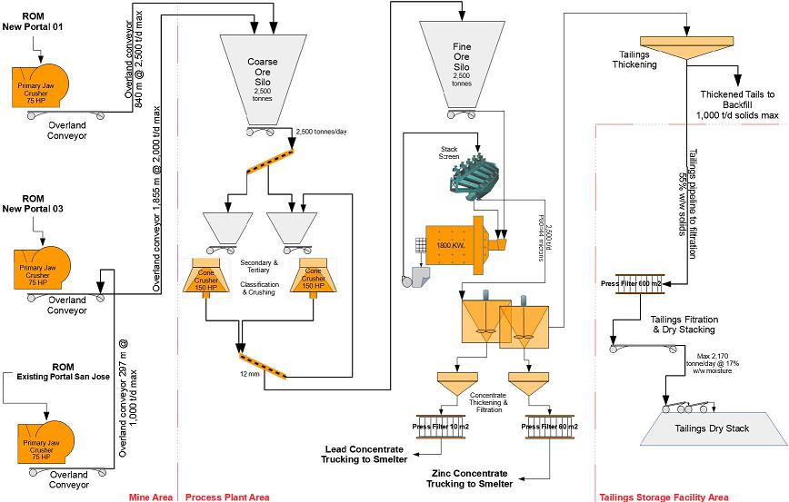
Source: SRK, 2017
Figure 17-1: Florida Canyon PEA Level Process Flow Sheet
| 144 |
18 Project Infrastructure
| 18.1 | Infrastructure and Logistics Requirements |
18.1.1 Access and Local Communities
Florida Canyon is a greenfield site with minimal infrastructure currently available. The operation is located in north central Peru (Figure 18-1) approximately 700 km north of the (capital, Lima. The Project is in a sparsely populated area approximately 39 km northwest of Pedro Luis Gallo (population approximately 3,000), the largest town with any infrastructure near the Project. There are several smaller communities located nearer to the proposed operation, but they have no developed infrastructure to support the project. A camp for employees and contractors will be required.
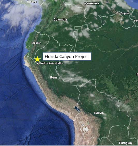
Source: Google Earth/SRK, 2017
Figure 18-1: Florida Canyon General Location
| 145 |
Access to the site is by paved road from Chiclayo (population approximately 740,000) located on the Pacific coast approximately 380 km to the west of Pedro Ruiz Gallo. A dirt road connects Pedro Ruiz with the district capitol of Shipasbamba where the project office and core storage facility is located. A 26 km newly constructed road connects Shipasbamba to the project area. This existing section of road will require upgrade to support construction and Project logistics including concentrate transport. Approximately 24 km of new road at the site will be required to allow access to the facilities and infrastructure. Figure 18-2 shows the new roads in the highlighted area near the Project. New road construction is in fairly rugged topography in an area of high rainfall that will require construction during the drier months to be efficient.
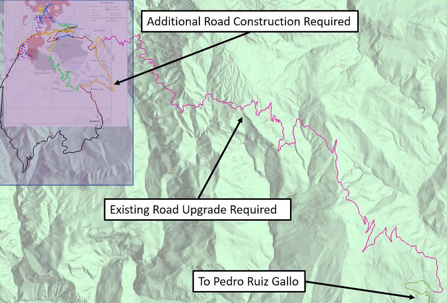
Source: SRK, 2017
Figure 18-2: Florida Canyon Existing and New Road Construction
18.1.2 Site Water Management
The operation will require water for use for processing, mining, dust suppression and potable consumption. The processing facility will utilize recycled water from the tailings facility and rainfall shed from the tailings for the majority of the processing needs. It is anticipated that there will be some ground water that will be encountered in the mine and captured in sumps and decantation basins for mine water needs.
| 146 |
Tesoro Creek, a small local drainage, has been used for domestic water supply by nearby residents. Clean water from this creek will be used for make-up process water, for fire suppression and for domestic requirements. It will be piped by gravity from the creek to a water storage tank. A small treatment plant will be utilized for potable water needs for the Project camp and other support areas.
Surface water control is discussed in the tailings Section 18.3.
18.1.3 Project Facilities
The project support infrastructure is shown in Figure 18-3. The facilities include the processing plant and associated infrastructure, mining infrastructure with portals, vent holes, road access to portals, tailings storage area, and support infrastructure including fuel storage, security, camp, power supply and distribution, and water supply and storage. Waste rock will be consumed in the construction of the tailings embankment so no separate waste rock storage is required.
| 147 |
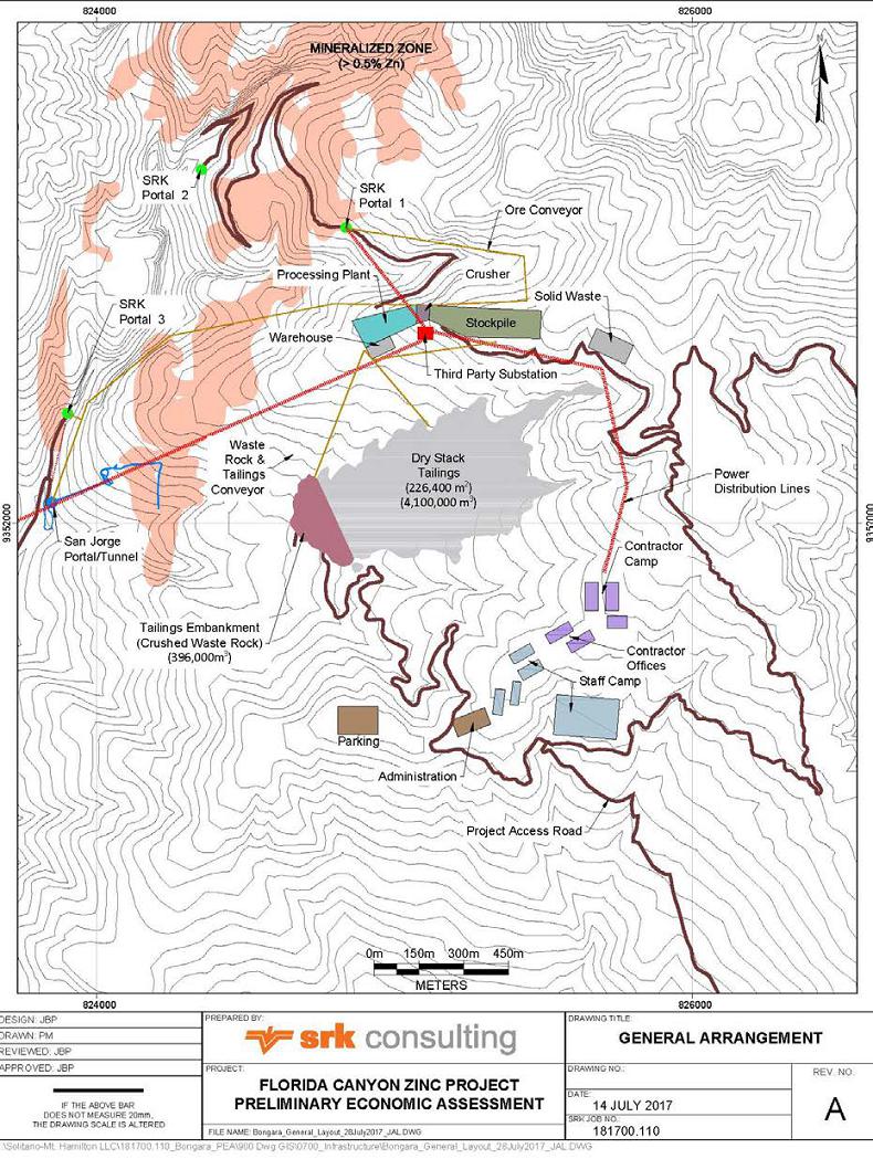
Source: SRK, 2017
Figure 18-3: Florida Canyon Site General Arrangement
| 148 |
Mine Operations and Support Facilities
The production-related project elements include a mine office, mine dry, and mine maintenance shops near the plant location to support the underground operations. Additional detail is included in Section
16. The mining method selected for the underground operation will require backfill consisting of cemented paste and waste rock, both cemented and unconsolidated. The capital cost of a paste backfill plant and operating cost of distribution is included in the economics for the Project. An allowance for a small cemented rock fill plant is also provided for two production periods when cemented rock fill is required for secondary stopes.
Process Support Facilities
The infrastructure at the process facilities include the plant, mill feed stockpile, secondary crusher, supply conveyors, primary crushers at the portals and an office/maintenance building. The plant facilities are discussed in Section 17.
Additional Support Facilities
The Project requires a camp to support the operation as it is remote. A 400-person camp with a cafeteria and recreation center will be required. Additional support facilities include a rescue and first aid building, warehouse, health/safety/environmental office, security gate house, truck scale, truck wash, laboratory, septic, and incinerator system. Two 50,000 liter fuel tanks and associated pump facilities will store fuel for use by the Project.
18.1.4 Power Supply and Distribution
There is currently no substantive line power near the site. SRK considered a diesel-powered generator option for power supply. However, a third-party supplier, Energoret S.A.C, has a hydropower generation and transmission development project that will be located in close proximity to the mine. The Energoret system will generate 20 MW of power from a plant on a tributary to the Utcubamba River. Energoret indicates that half of the project, approximately 10 MW, has already been committed. The plant is designed to provide power to the city of Bagua Grande, west of their project, and to Pedro Ruiz to the east of the Project. Energoret indicates that it will invest in a transmission line to the Florida Canyon mine site and a substation on site. Their capital estimate is US$25 million. Figure 18-4 shows the location of Energoret’s proposed hydroelectric plant, distribution lines to Bagua Grande and Pedro Ruiz as well as an extension to the Florida Canyon Project. The layout of the proposed system is shown in Figure 18-4 with the high voltage transmission lines delineated by the blue and white dotted line.
Neither Votorantim nor Solitario have entered into definitive negotiations with Energoret at this stage of study. Based on discussions with Energoret SRK estimated a power cost charge that would recover the capital expense for 6 MW of capacity of the plant plus the cost of transmission lines and a substation over the current 13 year life of the project including a risk premium and profit on both the capital and the operating costs. The estimated operating cost of power is US$0.084/kWhr.
SRK also included in the estimated capital cost for the project including a medium voltage power switchgear and 2.3 km of distribution lines to the processing plant and portals.
| 149 |
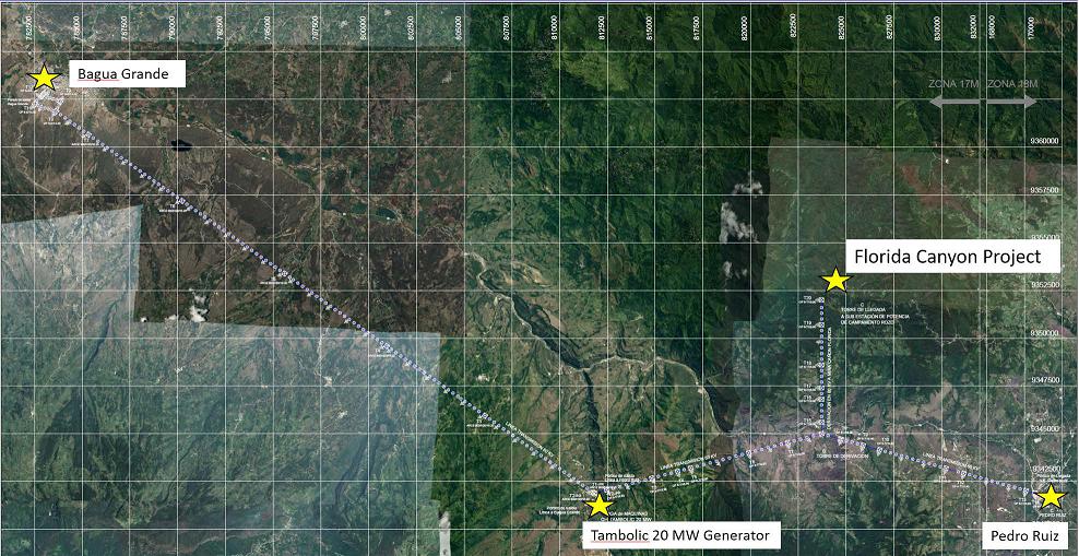
Source: Solitario, 2017
Figure 18-4: Florida Canyon Third Power Supply Alternative
| 150 |
| 18.2 | Project Logistics |
The Project will generate both lead and zinc concentrates which will be shipped by 30 t over-the-road trucks to market. Figure 18-5 shows a photograph of a typical 30 t truck.
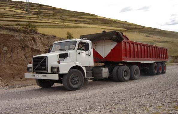
Source: Solitario, 2017
Figure 18-5: Typical 30 Tonne Concentrate Transport Truck
SRK has considered shipping to the ports at Paita, Chiclayo (Pimental), and Lima (Callao) as well as direct shipping to Votorantim’s Cajamarquilla Smelter near Lima. A high level trade-off study of concentrate transportation was prepared by SRK considering truck haulage, capital cost for additional port and/or handling facilities, and ocean freight/handling charges. This study indicated that the direct shipping option to Cajamarquilla was most cost effective. Figure 18-6 shows the locations of ports and the Cajamarquilla smelter.
| 151 |
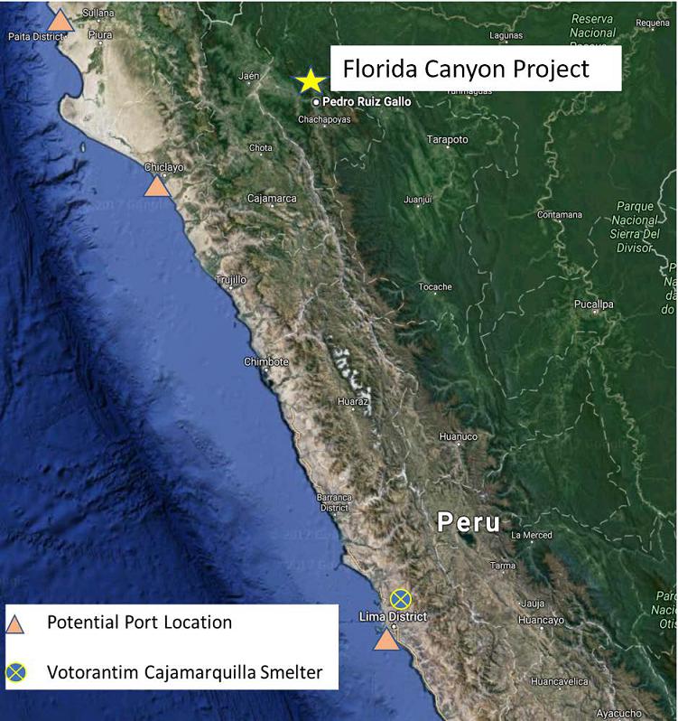
Source: SRK, 2017
Figure 18-6: Port and Smelter Locations
| 18.3 | Tailings Management |
The tailings storage facility (TSF) will be located in the valley to the south of the process plant as shown in Figure 18-3. The tailings will be filtered at the plant site to a “dry stack” condition (i.e. typical moisture content less than 20%). From the plant site, tailings will be transported to the TSF via overland conveyors.
| 152 |
Approximately 6.56 Mt of dry stack tailings will be will be produced over life of the mine and will have a final surface area of 266,400 m2. The TSF basin will be lined with 2 mm geomembrane. Approximately 1 m of topsoil will be excavated from the embankment and basin footprint and stockpiled for use during closure. All tailings not placed in the TSF will be utilized as backfill in the mine.
The TSF starter dam will be keyed into native ground approximately 4.5 m. The dam will have with a slope of 2:1 Horizontal:Vertical (H:V) and will be constructed of waste rock from underground and residual soils from the tailings basin. Additional raises will be constructed via an upstream method using waste rock or blasted rock from the tailings basin to construct the upstream containment berms. The upstream containment berms will have an overall slope of 3:1 H:V. Tailings will be placed using mobile mining equipment at a slope of 4:1 H:V. Upstream construction is suitable for this seismic environment because the tailings have been dewatered and will be compacted as they are placed.
An upstream diversion will be constructed to manage stormwater during operations and convey it downstream to be released beyond the toe of the dam. This diversion will consist of a 2 m deep and 5 m wide channel cut into native ground and lined with 300 mm rip rap.
| 153 |
19 Market Studies and Contracts
No specific market study has been conducted for this study. This PEA assumes metal prices based on the current spot market.
| 19.1 | Contracts and Status |
The Florida Canyon Project is a green field lead-zinc deposit that currently has no contracts that cover the sales of the projected lead and zinc concentrate production.
| 154 |
20 Environmental Studies, Permitting and Social or Community Impact
| 20.1 | Required Permits and Status |
20.1.1 Required Exploration Permits and Status
Environmental permits for mineral exploration programs are divided into two classes. Class I permits allow construction and drilling for up to 20 platforms with a maximum disturbance of 10 ha. A Class II permit provides for more than 20 drill locations or for a disturbance area of greater than 10 ha.
Class I permits require little more than a notification process for approval. Class II drilling permits require an environmental impact declaration (DIA), a permit for harvesting trees (if applicable), an archeological survey report (CIRA), a water use permit (ALA) and a Closure Plan.
Votorantim has previously filed applications for and received Class II permits for various phases of the Project and has filed and received the required associated permits. The 2017 review of existing exploration permit status indicates that only the archeological permits and the latest tree harvesting permit are still valid.
During exploration, Votorantim developed a Social Management Plan with several programs ongoing in the community including:
| · | Communication, Information and Coordination Program with Residents; |
| · | Attention to Concern, Claims and Conflict Resolution Program; |
| · | Support Program for Participatory Environmental Monitoring and Information Workshops; |
| · | Recruitment and Training Program for Local Labor; |
| · | Support Program for Sustainable Socioeconomic Development; and |
| · | Community Support Program in Education and Training. |
20.1.2 Required Mining Permits
Permitting requirements for mining include an Estudio de Impacto Ambiental (EIA) that describes in detail the mining plan and evaluates the impacts of the plan on environmental and social attributes of the property. Baseline studies include air quality, surface and groundwater quality, flora and fauna surveys, archeological surveys and a study of the social conditions of the immediate property and an area of interest that includes local communities. Many of the baseline studies required for mining have been completed by Votorantim. Public meetings are required in order that local community members can learn about and comment on the proposed operation. Social outreach has been clearly demonstrated during Votorantim’s exploration efforts as described above.
Specific authorizations, permits and licenses required for future mining include:
| · | EIA (as modified during the mine life); |
| · | Mine Closure Plan and Final Mine Closure Plan within two years of end of operation; |
| · | Certificate of Nonexistence of Archaeological Remains; |
| · | Water Use License (groundwater and/or surface water); |
| · | Water construction authorization; |
| · | Sewage authorization; |
| · | Drinking water treatment facility license; |
| 155 |
| · | Explosives use license and explosives storage licenses; |
| · | Controlled chemicals certificate; |
| · | Beneficiation concession; |
| · | Mining authorization; |
| · | Closure bonding; and |
| · | Environmental Management Plan approval. |
Information on environmental monitoring was limited in the SRK document review. Nevertheless, the need for additional monitoring in at least one dry and one wet period will be required for the EIA including terrestrial and aquatic fauna and flora and groundwater level and quality.
| 20.2 | Environmental Monitoring Results |
Environmental monitoring has been performed per the requirements to obtain the exploration permits, including the variables listed in the Table 20-1.
| 156 |
SRK Consulting (U.S.), Inc.
NI 43-101 Technical Report, Preliminary Economic Assessment – Florida Canyon Zinc Project Page 158
Table 20-1: Environmental Monitoring During Mining Exploration
| Factor | Legal Norm | Variables | Frequency |
|
Surface water quality (14 to 18 monitoring stations) |
Environmental standards for surface water quality as to D.S. Nº 002-2008-MINAM |
Temperature, Conductivity, pH, Total Suspended Solids (TSS), Oils and Grease, Cyanide – Total, Arsenic, Cadmium, Chromium VI, Copper, Iron, Lead, Mercury, Zinc, Sulphur, Nitrates, Phenols Dissolved oxygen thermotolerant coliforms total coliforms |
Quarterly |
|
Air quality (4 to 5 monitoring stations) |
Environmental standards for air quality: PM10, NO2, CO and O3 as to D.S. Nº 074-2001-PCM PM2,5 and SO2 as to D.S. N° 003-2008-MINAM lead in PM10, D.S. Nº 085-2003-PCM |
PM10-PM2.5-lead in PM 10- arsenic in PM10- gases. |
Quarterly |
| Noice (2 monitoring stations) | D.S. Nº 085-2003-PCM | Sound pressure | Quarterly |
|
Terrestrial fauna and flora |
D.S. Nº 004-2014 IUCN 2014 CITES |
various |
variable |
| Soil quality | Environmental standards for soil quality, D.S. N°002-2013 MINAM | As, Ba, Cd, Hg, Free CN | variable |
SRK, 2017
| 157 |
Information that SRK was able to review in the database was limited. Nevertheless, the need for additional monitoring in at least one dry and one wet period will be required for the EIA-d including terrestrial and aquatic fauna and flora and groundwater level and quality.
| 20.3 | Groundwater |
Groundwater has been studied by Hydro-Geo Consultores (2010) and Klohn Crippen Berger (2013). SRK reviewed these studies in context of underground mining. The mine is located in a high rainfall environment. Infiltration of surface water persists to approximately 50 m depth and recharges groundwater via structural pathways and interconnected karst features in dolomitized and de- dolomitized carbonate stratigraphy. The potentiometric surface has been determined by a series of piezometers. This groundwater surface follows the south-southwest flow direction of Florida Canyon and daylights at the river level in the canyon. Most of the planned mining of the flat mantos will occur above the water table. Steeper zones of mineralization, such as San Jorge and Sam will occur below the water table as will parts of the Karen Milagros mantos to the north. Local inflows may be encountered when crossing faults or intercepting karst features.
Impact to groundwater is expected to be minimal as underground surface exposures are minor and exposed sulfides are not acid generating. There are no groundwater wells required for processing or potable water supply. These needs will be met by surface water available from nearby Tesoro Creek.
| 20.4 | Environmental Issues |
The proposed underground mining operation is expected to have a small disturbance footprint compared to other mining methods. Waste rock from underground mining will be crushed and conveyed to the tailing storage facility (TSF) for use in construction of the tailings embankment. A small percentage of the waste rock will be used as underground backfill. As a result, there will be little or no surface area disturbance related to waste rock placement.
Waste rock generated from the mine and used in the tailings facility construction is composed of limestone and dolomite with a high neutralizing capacity. Most waste rock very low sulfide content so the potential for acid generation and metals leach is judged to be low. Nevertheless waste rock characterization study is recommended for future work.
The primary area of surface disturbance is related to tailings placement. As shown in Figure 18-3, the final tailings placement will have an area of 23.5 ha. Tailings also require geotechnical and geochemical stabilization during placement and closure. Tailings are predicted to have low amounts of iron sulfide and to be geochemically stable with respect to acid rock drainage. There is also substantial neutralization capacity in the carbonate host rocks to mitigate acid generation. Residual lead and zinc sulfides have low acid-generating capacity; however, they are subject to metal leaching and therefore require compaction during placement to minimize water infiltration. The closure plan to stabilize tailings is described later in this section of the report.
Water for processing is expected to be collected from surface streams and reclaimed from filtered tailings. There will be no need for groundwater consumption in the current processing plan. Groundwater will be intersected in deeper reaches of the underground mine. Most of this water will be used for dust suppression or piped to the mill to support comminution and flotation.
| 158 |
| 20.5 | Mine Closure |
A conceptual closure plan was developed to facilitate the calculation of the reclamation and closure costs to include in the PEA economic analysis. Closure designs and costs are based primarily on closure actions typically performed at similar sites.
| 20.3.1 | Post Mining Land Use |
Closure Design Objectives
| · | Promote positive and controlled drainage off the tailings surface and away from the dam face; |
| · | Maintain an erosional and geotechnically stable landform; |
| · | Promote native vegetation growth on the tailings surface, and |
| · | Create a closed facility that minimizes long-term monitoring and maintenance. |
| 20.3.2 | Portals and Vents |
Closure Design Objectives
| · | Prevent public access to underground workings. |
| · | Maintain an erosional and geotechnically stable landform. |
| · | Create a landform that visually approximates the surrounding landscape. |
| · | Promote native vegetation growth on the disturbed surface. |
| · | Create a closed facility that minimizes long-term monitoring and maintenance. |
Closure Tasks
| · | Portals and vents will be decommissioned by filling with waste rock or capping with a concrete bulkhead. Disturbed areas will be revegetated with native species. |
| 20.3.3 | Buildings and Infrastructure |
Closure Design Objectives
| · | Remove any facilities not needed for future use. |
| · | Maintain an erosional and geotechnically stable landform. |
| · | Create a landform that visually approximates the surrounding landscape. |
| · | Promote native vegetation growth on disturbed surfaces. |
| · | Create a closed facility that minimizes long-term monitoring and maintenance. |
Closure Tasks
| · | Buildings with no identified post-mining land use will be demolished and the debris will be hauled to the permitted landfill onsite. |
| · | Mill and conveyor parts with useful remaining life will be removed from the site and sold. The rest of the structure will be demolished and recyclable materials hauled offsite and the rest hauled to the permitted landfill onsite. |
| 159 |
| 20.3.4 | Roads and Miscellaneous Disturbance |
Closure Design Objectives
| · | Maintain an erosional and geotechnically stable landform. |
| · | Create a landform that visually approximates the surrounding landscape. |
| · | Promote native vegetation growth on the disturbed surface. |
| · | Create a closed facility that minimizes long-term monitoring and maintenance. |
Closure Tasks
| · | Roads not needed for an identified post-mining land use will be regraded to approximately original contours and revegetated with native plant species. |
| · | The main access roads and some internal mine roads may remain. Roads might be reconstructed to be smaller in width and include water control features to prevent erosion of the road bed. |
| · | Miscellaneous disturbance around other facilities will be regraded to approximately original contours and revegetated with native plant species. |
| 20.3.5 | Tailings Facility |
Closure Design Objectives
| · | Promote positive and controlled drainage off the tailings surface and away from the dam face. |
| · | Maintain an erosional and geotechnically stable landform. |
| · | Promote native vegetation growth on the tailings surface. |
| · | Create a closed facility that minimizes long-term monitoring and maintenance. |
Closure Tasks
The tailings dam face will be constructed of waste rock at either 2:1H:V or 3:1 H:V. As long as stormwater is directed away from the dam face and the slopes are not changed from design the facility will be erosionally and geotechnically stable. No further reclamation will be performed. Tailings operations and closure involve:
| · | During operations, at the end of mine-life, deposit tails such that the surface slopes up to 1% toward the center of the tailings; |
| · | Place 0.5 m of growth media on the tailings surface; |
| · | Construct a stormwater channel in the center of the tailings to convey water to the southwest corner upstream from the dam into native ground; |
| · | Construct a stormwater channel in native ground from the southwest corner of the tailings surface to spill into the natural drainage to the south; |
| · | Decommission the stormwater drain on the north side of the tailings facility and direct flow onto the tailings surface to be captured by the center stormwater ditch; and |
| · | Revegetate the tailings surface. |
| 20.6 | Post Closure Plans |
Post mining land use will approximate a natural park setting which could be used for livestock grazing and visually appears like the surrounding landscape. Generally, disturbed areas will be physically reclaimed and revegetated to approximate surrounding landforms. Disturbed areas will also be re-vegetated with native species. Some facilities may remain in place to support future access for exploration and/or further mineral development.
| 160 |
SRK recommends in future studies to design the tailings surface and spillway stormwater structure and evaluate options to reduce or eliminate the long-term obligation for monitoring and maintenance.
| 20.7 | Reclamation and Closure Cost Estimate |
Closure costs were calculated using the Standardized Reclamation Cost Estimator (SRCE) 2.0. The SRCE is a spreadsheet model that uses a first principles approach to calculate lengths, areas and volumes of common mine facilities and apply productivities for common mine equipment to estimate the time required. Unit costs for labor, materials and equipment are then applied to estimate a total cost.
Unit costs were as follows:
| · | Labor costs were factored from Nevada labor used by the Nevada Division of Environmental Protection (NDEP) for financial surety by multiplying by 40%; |
| · | Equipment and material costs were used without factoring from the NDEP costs used for financial surety; and |
| · | A fuel cost of US$1.24 per liter was used from the PEA documentation. |
Closure cost includes provision for General and Administrative, closure planning and engineering and staff oversite during the active closure. Provision is also included for monitoring and maintenance.
The estimated cost to close the mine is US$4,919,935 which will be spent over the two years following the end of mining. An additional long term monitoring and maintenance expense of US$829,835 will be required spread over 50 years starting in 2034. The total estimated closure cost is US$5,749,770.
| 20.8 | Post-Performance or Reclamations Bonds |
Reclamation bonds have not yet been defined or posted for the project.
| 20.9 | Social and Community |
From the social point of view, the Florida Canyon Project is developed on lands of the Community of Shipasbamba, located in the district of the same name, in the province of Bongará in the department of Amazonas. This community was registered in the Directory of Peasant Communities by R.S. 49 on December 17, 1959 (220 families).
In order to develop its exploration work, Votorantim Metais (VM) – Cajamarquilla S.A., has signed with the CC of Shipasbamba, biannual agreements from 2009 to 2017 for the use of 12,500 ha. In summary, VM - Cajamarquilla has performed the following actions with the:
Government
| · | Comply with the requirements demanded by the sector to obtain the necessary environmental permits to carry out its exploration activities. |
| · | In this context, it has developed several Citizen Participation Mechanisms in which the population has been informed about the objectives and scope of the Project and the type of relationship with the community that will be developed through its Community relations office. |
| 161 |
Community
| · | Agreements for the use of Surface Lands |
| o | From the point of view of social responsibility VM - Cajamarquilla, in order to be able to operate in the area in harmony with the local inhabitants, has signed bi-annual agreements for the Use of Land; |
| o | These establish the commitments and counter-commitments to which both parties are bound (company and community); |
| o | The last agreement signed by both parties expired in July 2017, and |
| o | The revised documents state that the necessary steps were being taken to sign the Convention for the period 2016-2018. |
| · | Community Relations: |
| o | VM - Cajamarquilla has developed a Social Management Plan with several Programs, on which detailed information is not available. It is assumed, from the photos included in a review of the company's activities that the programs are developing normally and are accepted by the community. These Programs are: |
| - | Social Management Plan and Community Relations; |
| - | Communication, Information and Coordination Program with Residents; |
| - | Attention to Concern, Claims and Conflict Resolution Program; |
| - | Support Program for Participatory Environmental Monitoring and Information Workshops; |
| - | Recruitment and Training Program for Local Labor; |
| - | Support Program for Sustainable Socioeconomic Development; and |
| - | Community Support Program in Education and Training. |
21 Capital and Operating Costs
As part of the Florida Canyon valuation exercise, SRK prepared an estimate of both capital and operating costs associated with the designed mineable resources production schedule. This section of the report presents and details these estimates of Capital Expenditure and Operating Expenditure. All estimates are based on yearly inputs of physicals and all financial data is second quarter 2017 and currency is in U.S. dollars (US$), unless otherwise stated.
The use of “ore” in the summary of tables of this PEA is a relative mineable material estimated. Ore, by definition, can only be ascribed to economic mineralization supported by Mineral Reserves.
| 21.1 | Capital Cost Estimates |
The Florida Canyon Project is a green field lead-zinc deposit and the estimate of capital includes both an estimate of initial capital investment to install and commission the mine and a sustaining capital to maintain the equipment and expanding any supporting infrastructure necessary to continue running the project until the end of the projected production schedule. The estimate of capital was broken down into the following main areas:
| · | Mining areas access development and vent raises; |
| · | Underground Mining Equipment; |
| · | Surface crushing and conveying systems; |
| · | Offsite Infrastructure; |
| · | Site Facilities; |
| · | Process Plant; |
| · | Power Supply; |
| · | Water Supply; |
| · | Backfill Infrastructure; |
| · | Cement Rockfill Infrastructure; |
| · | Tailings Storage Facility; |
| · | Owner’s Cost; and |
| · | Closure and Post-Closure Monitoring. |
The capital cost estimates developed for this study comprise the costs associated with the engineering, procurement, construction and commissioning required for all items. The cost estimate was based SRK’s experience with similar projects installed in the region or estimates of cost specifically prepared for the project under a first principles basis. The work indicates that the project will require an initial capital of US$213.7 million and a sustaining capital of US$81.9 million Table 21-1 summarizes the estimate of capital.
| 162 |
Table 21-1: Florida Canyon Capital Estimate Summary
| Description | Initial (US$000’s) | Sustaining (US$000’s) | LoM (US$000’s) |
| Development | 12,293 | 35,741 | 48,033 |
| Vent Raises | 686 | 672 | 1,358 |
| Underground Mining Equipment | 24,625 | 2,474 | 27,099 |
| Surface Crushing & Conveying | 1,430 | 0 | 1,430 |
| Offsite Infrastructure | 16,227 | 0 | 16,227 |
| Site Facilities | 14,697 | 0 | 14,697 |
| Process Plant | 60,000 | 0 | 60,000 |
| Power Supply | 2,472 | 0 | 2,472 |
| Water Supply | 250 | 0 | 250 |
| Backfill Infrastructure | 13,200 | 0 | 13,200 |
| Cement Rockfill Infrastructure | 200 | 0 | 200 |
| Tailings Storage Facility | 12,854 | 11,814 | 24,668 |
| Owner's | 14,595 | 0 | 14,595 |
| Contingencies | 40,138 | 0 | 40,138 |
| Sustaining Capital | 0 | 26,272 | 26,272 |
| Closure | 0 | 4,920 | 4,920 |
| Post-Closure Monitoring | 0 | 830 | 830 |
| Total Capital | $213,667 | $82,722 | $296,389 |
Source: SRK, 2017
21.1.1 Basis for Capital Cost Estimates
The cost associated with mining area access development and the construction of vent raises was based on the preparation of a mineable resources production schedule that included a design of meters of development and meters of vent raises, these were combined with the following unit costs to result in the cost estimate:
| · | Development: US$1,500/m; and |
| · | Vent Raises: US$2,200/m. |
These unit costs are based on data from comparable underground mines also located in Peru or other South American areas with similar mining conditions.
A schedule of acquisition of underground mining equipment specific to the production schedule was prepared, Table 21-2 presents the unit costs and acquisitions of these equipment.
Table 21-2: Florida Canyon Underground Mine Equipment Acquisition Schedule
| Equipment |
UnitCost (US$) |
TotalCost (US$) |
Acquisition Year | |||||||||||
| 1 | 2 | 3 | 4 | 5 | 6 | 7 | 8 | 9 | 10 | 11 | 11 | |||
| LH Stope DTH Drills | 432,000 | 864,000 |
3 |
1 | 1 |
1 |
1 |
1 | ||||||
| LH Production LHD | 900,000 | 2,700,000 | 2 | 1 | ||||||||||
| Production Jumbo (D&F/C&F) | 644,000 | 3,864,000 | 3 | 2 | ||||||||||
| D&F/C&F Production LHD | 675,000 | 4,050,000 | 3 | 1 | 2 | |||||||||
| Horizontal Development Jumbos (2 boom) | 644,000 | 2,576,000 | 1 | |||||||||||
| Development LHD | 900,000 | 3,600,000 | 3 | 1 | ||||||||||
| Haul Trucks | 765,000 | 4,590,000 | 4 | 2 | ||||||||||
| Rock Bolter | 829,000 | 1,658,000 | 1 | 1 | ||||||||||
| Anfo Loader | 437,000 | 437,000 | 1 | |||||||||||
| Miscellaneous/Service Vehicles | 320,000 | 1,600,000 | 3 | 2 | ||||||||||
| Light Vehicles/General | 40,000 | 200,000 | 3 | 2 | ||||||||||
| Ventilation Fans | 240,000 | 960,000 | 1 | 1 | ||||||||||
Source: SRK, 2017
The process plant cost estimate is based on data from similar flotation plants with the same capacity and same region. This investigation resulted in an estimate of about US$60 million.
The cost associated with the required surface crushing and conveying was based on required distances and elevation gain to cover. These include the movement of mineralized material from three mine portals to the plant feed area and some waste material that will be used to build the embankment for the tailings storage facility. This investigation resulted in an estimate of around US$1.4 million.
Offsite-infrastructure, site infrastructure, power supply, water supply and backfill infrastructure cost estimates were prepared based the required structures costs from comparable operations. It should be noted that this study assumes that a third-party is planning to build a hydro power plant that will provide power to the project. A company has approached Solitario to offer this option, including the construction of the transmission line and project substation. Table 21-3 summarizes the basis of these cost estimates.
| 163 |
SRK Consulting (U.S.), Inc.
NI 43-101 Technical Report, Preliminary Economic Assessment – Florida Canyon Zinc Project Page 167
Table 21-3: Florida Canyon Offsite, Site, Power, Water and Backfill Infrastructure
| Type | Description | Quantity | Units |
Unit Cost (US$) |
Units | Total Cost (US$ millions) |
| Offsite Infrastructure | Access Road New Construction | 15.6 | km | 339,000 | US$/km | 5,285,996 |
| Offsite Infrastructure | Access Road Upgrade | 33.1 | km | 330,500 | US$/km | 10,940,724 |
| Energy | Fuel Tanks (50k liters each) | 2 | each | 83,333 | US$/tank | 166,667 |
| Energy | Fuel pumps and associated facilities | 1 | LS | 225,000 | US$/system | 225,000 |
| Energy | Medium Voltage Powerlines (on site) | 2.3 | km | 900,000 | US$/km | 2,080,800 |
| Water Supply | Potable Water Treatment | 1 | each | 100,000 | US$/unit | 100,000 |
| Facilities | Mine Office | 1 | each | 858,479 | US$/unit | 858,479 |
| Facilities | Mine Dry | 1 | each | 822,418 | US$/unit | 822,418 |
| Facilities | Rescue and First Aid | 1 | each | 622,950 | US$/unit | 622,950 |
| Facilities | Warehouse | 1 | each | 1,701,300 | US$/unit | 1,701,300 |
| Facilities | Health/Safety/Environmental Office | 1 | each | 487,945 | US$/unit | 487,945 |
| Facilities | Mine Maintenance Shops | 1 | each | 4,159,230 | US$/unit | 4,159,230 |
| Facilities | Administrative Building | 1 | each | 1,212,554 | US$/unit | 1,212,554 |
| Water Supply | Water System Tank and piping | 1 | each | 150,000 | US$/unit | 150,000 |
| Facilities | Security Gatehouse | 1 | each | 298,204 | US$/unit | 298,204 |
| Facilities | Truck Scale | 1 | each | 159,515 | US$/unit | 159,515 |
| Facilities | Truck Wash | 1 | each | 280,239 | US$/unit | 280,239 |
| Facilities | Personnel Camp with Cafeteria, Rec Center, 400 people | 1 | LS | 3,000,000 | US$/unit | 3,000,000 |
| Facilities | Laboratory | 1 | each | 418,896 | US$/unit | 418,896 |
| Facilities | Sewer | 1 | each | 400,000 | US$/unit | 400,000 |
| Facilities | Incinerator System | 1 | each | 275,000 | US$/unit | 275,000 |
| Backfill | Plant Cost | 1 | LS | 10,300,000 | US$/each | 10,300,000 |
| Backfill | Underground | 1 | LS | 2,900,000 | US$/each | 2,900,000 |
Source: SRK, 2017
| 164 |
Cement will be added to underground waste rock and used to fill designated primary fill areas, this will be done by underground installed facilities that are estimated to cost roughly US$200,000.
SRK prepared a design for a dry stack tailings storage facility to contain all the filtered tailings generated by the lead and zinc concentrates production. The cost estimate included the preparation of a stage construction using borrow material from the underground mine and construction area. This resulted in a total cost of US$24.7 million, which is split US$12.9 million initial capital and US$11.8 million sustaining capital. The relevant section of this report contains more details about this tailings storage facility design.
Closure costs were estimated by SRK as US$4.9 million for the actual closure and about US$830,000 for post closure site monitoring. Details of this estimate can be found in the relevant section of this report.
Other capital cost estimates include the following:
| · | Owner’s cost: Estimate of about 10% of initial capital, excluding development and vent raises; |
| · | Sustaining Capital: 2% of initial capital, excluding development, vent raises and owner’s costs; and |
| · | Contingencies: 25% contingencies were applied to initial capital, excluding development and vent raises and owner’s costs. |
| 21.2 | Operating Cost Estimates |
SRK prepared the estimate of operating costs for the associated mineable resources production schedule. These costs were subdivided into the following categories:
| · | Mining Operating Expenditure; |
| · | Processing Operating Expenditure; and |
| · | G&A Operating Expenditure. |
The resulting LoM cost estimate is presented in Table 21-4.
Table 21-4: Florida Canyon Operating Costs Summary
| Description | LoM (US$000’s) | LoM (US$/t-Ore) | LoM (US$/lb-Zn) |
| Underground Mining | 228,547 | 20.43 | 0.16 |
| Process | 144,063 | 12.88 | 0.10 |
| G&A | 39,153 | 3.50 | 0.03 |
| Total Operating | 411,764 | 36.81 | 0.29 |
Source: SRK, 2017
21.2.1 Basis for Operating Cost Estimates
The prepared estimates that compose the operating costs consist of domestic and international services, equipment, labor, etc. Where required, the following were included:
| · | Value added tax; |
| · | Freight; and |
| · | Duty. |
| 165 |
No specific work schedule has been defined for the mine, plant and site operations.
All of the operating cost estimates are based on the quantities associated with the production schedule, including the following:
| · | Run of Mine; |
| · | Primary and Secondary Backfill; and |
| · | Plant Feed. |
Unit costs from similar projects in the same region or in the Americas, adjusted for labor and consumables differences, were used to estimate the LoM operating costs. All operating costs include supervision staff, operations labor, maintenance labor, consumables, electricity, fuels, lubricants, maintenance parts and any other operating expenditure identified by contributing engineers. The following unit costs were used to calculate the operating costs:
| · | Underground Mining: US$ 15.30/t-RoM; |
| · | Primary Cement Rockfill: US$22.18/m3; |
| · | Primary Cement Pastefill: US$26.23/m3; |
| · | Secondary Cement Pastefill: US$18.13/m3; and |
| · | Processing: US$12.00/t-Feed. |
General and Administration costs were considered as 10% of the other operating costs, which resulted in a unit rate of US$3.50/t-RoM.
| 166 |
22 Economic Analysis
The financial results presented here are based on annual inputs from the production schedule prepared by SRK. All financial data is second quarter 2017 and currency is in U.S. dollars (US$), unless otherwise stated.
| 22.1 | External Factors |
Florida Canyon does not hold contracts for the provision of its products. The costs and discounts associated with the sales of the products are based on recent information from similar operations. This study was prepared under the assumption that the project will sell the following products.
| · | Lead concentrate; and |
| · | Zinc concentrate; |
It was also considered that the lead concentrate also contains payable amounts of silver.
Assumed prices are based on current market spot prices. Table 22-1 presents the prices used in the cashflow model, which were also used for mineable resource calculations.
Table 22-1: Florida Canyon Price Assumptions
| Description | Value | Unit |
| Silver | 16.50 | US$/oz |
| Lead | 1.00 | US$/lb |
| Zinc | 1.20 | US$/lb |
Source: Solitario, 2017
Treatment charges and net smelter returns (NSR) terms for each type of product are summarized in Table 22-2.
Table 22-2: Florida Canyon Net Smelter Return Terms
| Description | Value | Units |
| Lead Concentrate | ||
| Treatment Charges | 210.10 | US$/t-conc. |
| Payable Lead | 95.0% | No deducts |
| Silver Smelting & Refining Charges | 1.50 | US$/oz-Ag |
| Payable Silver | 95.0% | No deducts |
| Zinc Concentrate | ||
| Treatment Charges | 203.00 | US$/t-conc. |
| Payable Zinc | 85.0% | No deducts |
Source: SRK, 2017
It was assumed that zinc concentrates will be trucked to the Cajamarquilla smelter owned by Votorantim near Lima, Peru. Lead concentrates will be trucked to the Port of Callao near Lima and shipped overseas to a lead smelter. It was assumed that the concentrates will have an average moisture content of 8%. Table 22-3 presents the calculated transportation costs considered for each product.
| 167 |
Table 22-3: Florida Canyon Product Logistics Cost
| Items | Value | Unit |
| Lead Concentrate | 87.05 | US$/t |
| Zinc Concentrate | 51.08 | US$/t |
Source: SRK, 2017
| 22.2 | Main Assumptions |
Common prices for consumables, labor, fuel, lubricants and explosives were used by all engineering disciplines to derive capital and operating costs. Included in the labor costs are shift differentials, vacation rotations, all taxes and the payroll burdens. All currency is in U.S. dollars (US$) unless otherwise stated.
The pre-production period was estimated to be two years. This should be enough to develop access to mining areas, install and commission the plant and site infrastructure. Mine production is based on an average assumed LoM mine material movement of 2,358 t-ore/d (365 days/yr basis). The mine schedule does not include stockpiling as all blending of run of mine (RoM) is done in the mine. Table 22-4 presents the LoM mine assumptions.
Table 22-4: Florida Canyon Mine Production Assumptions
| Description | Value | Units |
| Mine Production | ||
| Underground Ore | 11,187 | kt |
| Total Material | 11,187 | kt |
| Avg. Daily Capacity | 2,358 | t per day |
| Stripping Ratio | N/A | w:o |
| RoM Grade | ||
| Silver | 11.3 | g/t |
| Lead | 0.90% | % |
| Zinc | 8.34% | % |
| Contained Metal | ||
| Silver | 4,068 | koz |
| Lead | 222,347 | klb |
| Zinc | 2,057,796 | klb |
Source: SRK, 2017
The average mill feed is also 2,358 t/d (365 days/yr basis) over the LoM. The mill feed has an average head grade of 11.3 g/t Ag, 0.90% Pb and 8.34% Zn. The processing circuit is designed to recover a lead concentrate and a zinc concentrate, the lead concentrate also contains payable amounts of silver. Table 22-5 presents the projected LoM plant production.
| 168 |
Table 22-5: Florida Canyon Mill Production Assumptions
| Description | Value | Units |
| RoM Ore Milled | 11,187 | kt |
| Daily Capacity | 2,358 | tperday |
| Lead Concentrate | ||
| Moisture Content | 8% | |
| Concentrate Silver Grade | 436 | g/t |
| Concentrate Lead Grade | 50% | % |
| Concentrate Zinc Grade | 0% | % |
| Recovery | ||
| Silver | 52% | |
| Lead | 74% | |
| Zinc | 0% | |
| Concentrate Yield | 150 | kt(dry) |
| Zinc Concentrate | ||
| Moisture Content | 8% | |
| Concentrate Silver Grade | 0 | g/t |
| Concentrate Lead Grade | 0.0% | % |
| Concentrate Zinc Grade | 50% | % |
| Recovery | ||
| Silver | 0% | |
| Lead | 0% | |
| Zinc | 80% | |
| Concentrate Yield | 1,491 | kt(dry) |
Source: SRK, 2017
| 22.3 | Taxes, Royalties and Other Interests |
The analysis of the Florida Canyon Project includes a total of 30% of income taxes over taxable income. Losses carried forward are used when possible, limited to 50% of profits. A depreciation schedule was calculated by SRK assuming a ten-year straight line depreciation.
The Project includes payment of two types of governmental royalties, the first called a mining royalty and the second called a special mining tax. Both royalties are calculated as a rate depending on the ratio between the Earnings Before Interest and Taxes (EBIT) and the Net Revenue. This rate is applied on top of the EBIT, with the difference that the mining royalty can be replaced by a minimum rate of 1% over the net revenue, in case this 1% is higher than the mining royalty rate over the EBIT. The rates for each royalty are presented in Table 22-6.
Table 22-6: Florida Canyon Royalty Rates
| EBIT (%) | Special Mining Tax | Mining Royalty | ||
| Marg. (%) | Cum. (%) | Marg. (%) | Cum. (%) | |
| 0.00 | 0.00 | 0.00 | 0.00 | 0.00 |
| 10.00 | 2.00 | 0.20 | 1.00 | 0.10 |
| 15.00 | 2.40 | 0.32 | 1.75 | 0.19 |
| 20.00 | 2.80 | 0.46 | 2.50 | 0.31 |
| 25.00 | 3.20 | 0.62 | 3.25 | 0.48 |
| 30.00 | 3.60 | 0.80 | 4.00 | 0.68 |
| 35.00 | 4.00 | 1.00 | 4.75 | 0.91 |
| 40.00 | 4.40 | 1.22 | 5.50 | 1.19 |
| 45.00 | 4.80 | 1.46 | 6.25 | 1.50 |
| 50.00 | 5.20 | 1.72 | 7.00 | 1.85 |
| 55.00 | 5.60 | 2.00 | 7.75 | 2.24 |
| 60.00 | 6.00 | 2.30 | 8.50 | 2.66 |
| 65.00 | 6.40 | 2.62 | 9.25 | 3.13 |
| 70.00 | 6.80 | 2.96 | 10.00 | 3.63 |
| 80.00 | 7.60 | 3.70 | 11.50 | 4.74 |
| 85.00 | 8.00 | 4.10 | 12.00 | 5.34 |
| 90.00 | 8.40 | 4.52 | 12.00 | 5.34 |
Source: SRK, 2017
| 22.4 | Results |
The valuation results of the Florida Canyon Project indicate that the Project has a potential present value of approximately US$198 million, with an Internal Rate of Return (IRR) of 25%, based on an 8% discount rate. The operation will have two years of negative free cash flow, as it has to be constructed in this period. Even with some of the capital spent in the first year of operation, it is projected that this year will have a positive free cash flow. This economic analysis indicates that the investment payback should occur 2. 6 years from the start of the commercial production. The estimate free cash flow of the project is presented in Figure 22-1.
| 169 |
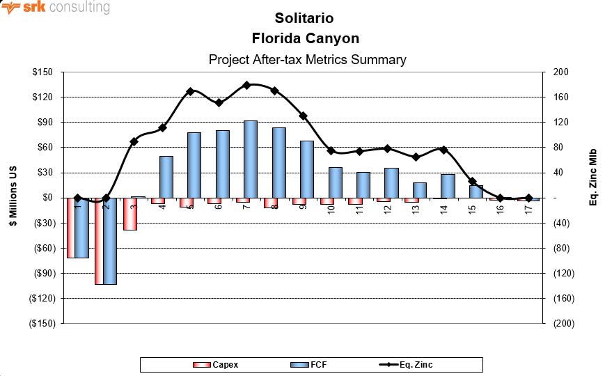
Source: SRK, 2017
Figure 22-1: Florida Canyon After-Tax Free Cash Flow and Equivalent Metal Production
Indicative economic results are presented in Table 22-7, the table evidences that zinc is responsible for the clear majority of the revenue generation and the underground mining cost is the heaviest burden on the operation, followed by the mineral processing cost as a far second.
| 170 |
Table 22-7: Florida Canyon Indicative Economic Results (Dry Basis)
| Description | Value | Units |
| Market Prices | ||
| Silver | 16.50 | US$/oz |
| Lead | 1.00 | US$/lb |
| Zinc | $1.20 | US$/lb |
| Estimate of Cash Flow (all values in US$000s) | ||
| Concentrate Net Return | $/oz-Ag | |
| Silver Sales | $32,957 | $0.02 |
| Lead Sales | $156,937 | $0.11 |
| Zinc Sales | $1,675,977 | $1.20 |
| Total Revenue | $1,865,871 | $1.34 |
| Treatment, Smelting and Refining Charges | ($337,076) | |
| Freight, Impurities & Third Parties | ($96,935) | ($0.07) |
| Gross Revenue | $1,431,860 | |
| Royalties | ($61,734) | ($0.04) |
| Net Revenue | $1,370,126 | |
| Operating Costs | ||
| Open Pit Mining | $0 | $0.00 |
| Underground Mining | ($228,547) | ($0.16) |
| Process | ($144,063) | ($0.10) |
| G&A | ($39,153) | ($0.03) |
| Ordinary Rights | $0 | $0.00 |
| Total Operating | ($411,764) | ($0.29) |
| Operating Margin (EBITDA) | $958,362 | |
| Initial Capital | ($213,667) | |
| LoM Sustaining Capital | ($82,722) | |
| Income Tax | ($224,873) | |
| After Tax Free Cash Flow | $437,100 | |
| Payback | 2.59 | years |
| After-Tax IRR | 24.7% | |
| NPV @: 8% | $197,521 |
Source: SRK, 2017
| 171 |
Table 22-8 shows annual production and revenue forecasts for the life of the project. All production forecasts, material grades, plant recoveries and other productivity measures were developed by SRK and Solitario.
Table 22-8: Florida Canyon LoM Annual Production and Revenues
|
Period |
RoM (Mt) | Plant Feed (Mt) |
Lead Conc. (kt) |
Zinc Conc. (kt) |
Free Cash Flow (US$ millions) | Discounted Cash Flow (US$ millions) |
| -2 | 0.00 | 0.00 | 0.00 | 0.00 | (72) | (72) |
| -1 | 0.00 | 0.00 | 0.00 | 0.00 | (103) | (96) |
| 1 | 0.73 | 0.73 | 9.06 | 95.86 | 2 | 2 |
| 2 | 0.91 | 0.91 | 11.07 | 119.02 | 50 | 40 |
| 3 | 0.91 | 0.91 | 14.87 | 180.57 | 78 | 57 |
| 4 | 0.91 | 0.91 | 17.73 | 161.95 | 80 | 54 |
| 5 | 0.92 | 0.92 | 14.78 | 191.19 | 92 | 58 |
| 6 | 0.91 | 0.91 | 15.26 | 181.90 | 84 | 49 |
| 7 | 0.91 | 0.91 | 15.80 | 138.77 | 68 | 37 |
| 8 | 0.91 | 0.91 | 12.22 | 80.34 | 36 | 18 |
| 9 | 0.92 | 0.92 | 11.73 | 79.35 | 31 | 14 |
| 10 | 0.91 | 0.91 | 11.24 | 83.01 | 35 | 15 |
| 11 | 0.92 | 0.92 | 4.82 | 69.77 | 18 | 7 |
| 12 | 0.91 | 0.91 | 7.76 | 81.33 | 28 | 10 |
| 13 | 0.40 | 0.40 | 3.53 | 27.54 | 14 | 5 |
| 14 | 0.00 | 0.00 | 0.00 | 0.00 | 0 | 0 |
| 15 | 0.00 | 0.00 | 0.00 | 0.00 | (3) | (1) |
| 16 | 0.00 | 0.00 | 0.00 | 0.00 | 0 | 0 |
| 17 | 0.00 | 0.00 | 0.00 | 0.00 | 0 | 0 |
| Total | 11.19 | 11.19 | 150 | 1,491 | 437 | 198 |
Source: SRK, 2017
| 172 |
The Florida Canyon project is mainly a zinc project, as this metal represents roughly 90% of the total projected revenue. The remainder of the revenue is related to lead and silver, where both these metals are by-products, as none represent a minimum of 20% of the revenue projection. Figure 22-2 presents the revenue broken down by each metal.
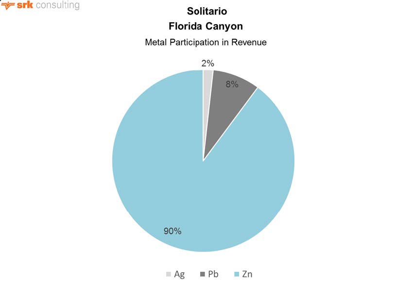
Source: SRK
Figure 22-2: Metal Participation in Revenue – Florida Canyon
Project cash costs are reported under an equivalent zinc production. All-in costs for zinc, including initial and sustaining capital costs, are estimated at US$0.73/Zn-lb. Considering byproduct credits for lead and silver, all-in zinc cost is US$0.47/Zn-lb. Table 22-9 presents the composition of the Florida Canyon cash costs.
| 173 |
Table 22-9: Florida Canyon Cash Costs
| Cash Costs | US$000's |
| Direct Cash Cost | |
| Underground Mining Cost | $228,547 |
| Process Cost | $144,063 |
| Site G&A Cost | $39,153 |
| Ordinary Rights | $0 |
| Treatment Charges | $334,080 |
| Smelting & Refining Charges | $2,996 |
| Freight | $96,935 |
| By-Product Credits | ($189,894) |
| Direct Cash Costs | $655,881 |
| US$/t-ore | $58.63 |
| US$/lb-Zn | $0.47 |
| Indirect Cash Cost | |
| Royalties | $61,734 |
| Exploration Expense | $0 |
| Social Responsibility/Community Relations Expense | $0 |
| Indirect Cash Costs | $61,734 |
| US$/t-ore | $5.52 |
| US$/lb-Zn | $0.04 |
| Direct + Indirect Cash Costs | $717,615 |
| US$/t-ore | $64.15 |
| US$/lb-Zn | $0.51 |
| Sustaining Capital Cash Cost | |
| Sustaining Capital | $82,722 |
| Sustaining Cash Costs | $82,722 |
| US$/t-ore | $7.39 |
| US$/lb-Zn | $0.06 |
| All-In Sustaining Cash Costs | $800,337 |
| US$/t-ore | $71.54 |
| US$/lb-Zn | $0.57 |
| Initial Capital Cash Cost | |
| Initial Capital | $213,667 |
| Initial Capital Cash Costs | $213,667 |
| US$/t-ore | $19.10 |
| US$/lb-Zn | $0.15 |
| All-In Cash Costs | $1,014,004 |
| US$/t-ore | $90.64 |
| US$/lb-Zn | $0.73 |
Source: SRK, 2017
| 174 |
| 22.5 | Base Case Sensitivity Analysis |
Sensitivity on discount rates and different metal prices scenarios were conducted. The results are presented in Figure 22-3 and Figure 22-4.
Figure 22-3 presents the behavior of the accumulated after-tax net present value, where:
| · | Distressed metal prices are 20% lower than neutral prices; |
| · | Neutral metal prices as presented in this section; and |
| · | Robust metal prices are 20% higher than neutral prices. |
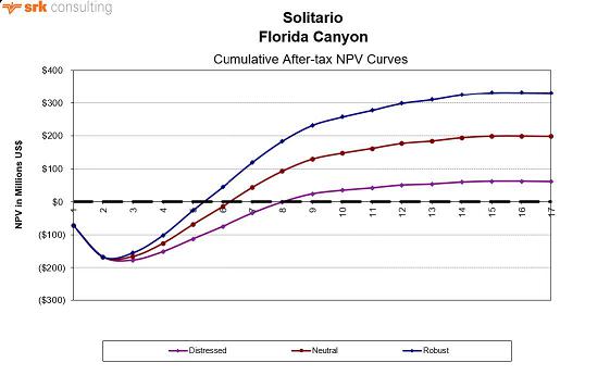
Source: SRK, 2017
Figure 22-3: Florida Canyon Cumulative NPV Curves (after tax)
| 175 |
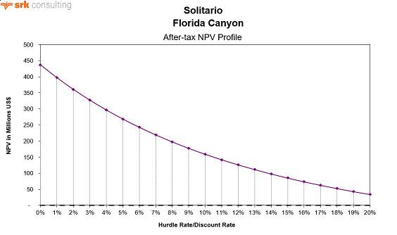
Source: SRK, 2017
Figure 22-4: Florida Canyon NPV Sensitivity to Hurdle Rate
A sensitivity analysis on variation of Project costs, both capital and operating, and metal prices indicated that the cash generating is mostly sensitive to the reduction of metal prices, or possibly loss on metal recovery, and secondly to the increase of capital costs. A chart of typical sensitivities is provided in Figure 22-5.
| 176 |
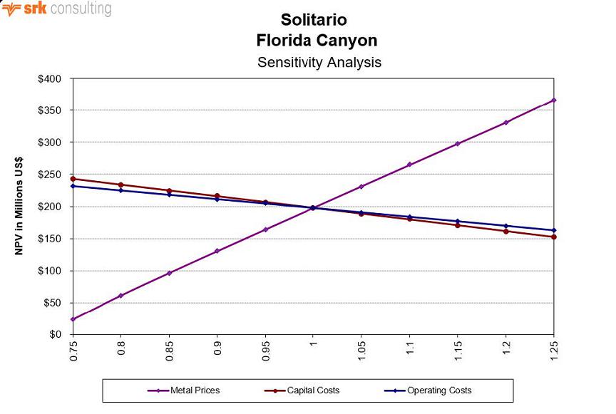
Source: SRK, 2016
Figure 22-5: Florida Canyon NPV Sensitivity (US$000’s)
| 22.6 | Conservative Metal Price Alternative Analysis |
The owners requested SRK to evaluate the Florida Canyon Project under a specific alternate metal price structure. This forecast includes a new set of long term metal prices, which are considerably lower than current spot metal prices for zinc and lead. The alternative pricing is presented in Table 22-10.
Table 22-10: Alternate Market Forecast Metal Prices
| Description | Value | Unit |
| Silver | 18.91 | US$/oz |
| Lead | 0.88 | US$/lb |
| Zinc | 1.06 | US$/lb |
Source: SRK, 2017
The owners also asked that for these market conditions the project be evaluated with a higher discount rate of 9%.Only these metal prices and the discount rate were changed in this alternative valuation. Other inputs and estimates were maintained the same as the base case, including:
| · | Mineable Resources; |
| · | Process Recoveries; |
| · | On-Site and Off-Site Operating Costs; |
| · | Capital Costs; and |
| · | Net Smelter Terms. |
22.6.1 Impact to Mine Planning
SRK investigated the impact of using the more conservative economic inputs on mine planning, specifically, the NSR calculation. Using the new NSR calculation and applying it to the mine plan resource presented in this document, has the effect of lowering the overall average NSR by 23%. Overall, the revenue generated from the mine plan resource is 77% of the original assumptions.
Figure 22-6 shows the mine plan resource, colored by the sensitivity NSR (US$/t). The economic cut- off is approximately US$40/t-NSR. Dark blue mining areas in the figure are now below cut-off and light blue areas are marginal. Using the sensitivity NSR, when all areas are combined, the mine plan is still economic. Given these new sensitivity inputs, the mine plan could be optimized to eliminate the un- economic material and minimize the amount of marginal material in the mine plan.
| 177 |
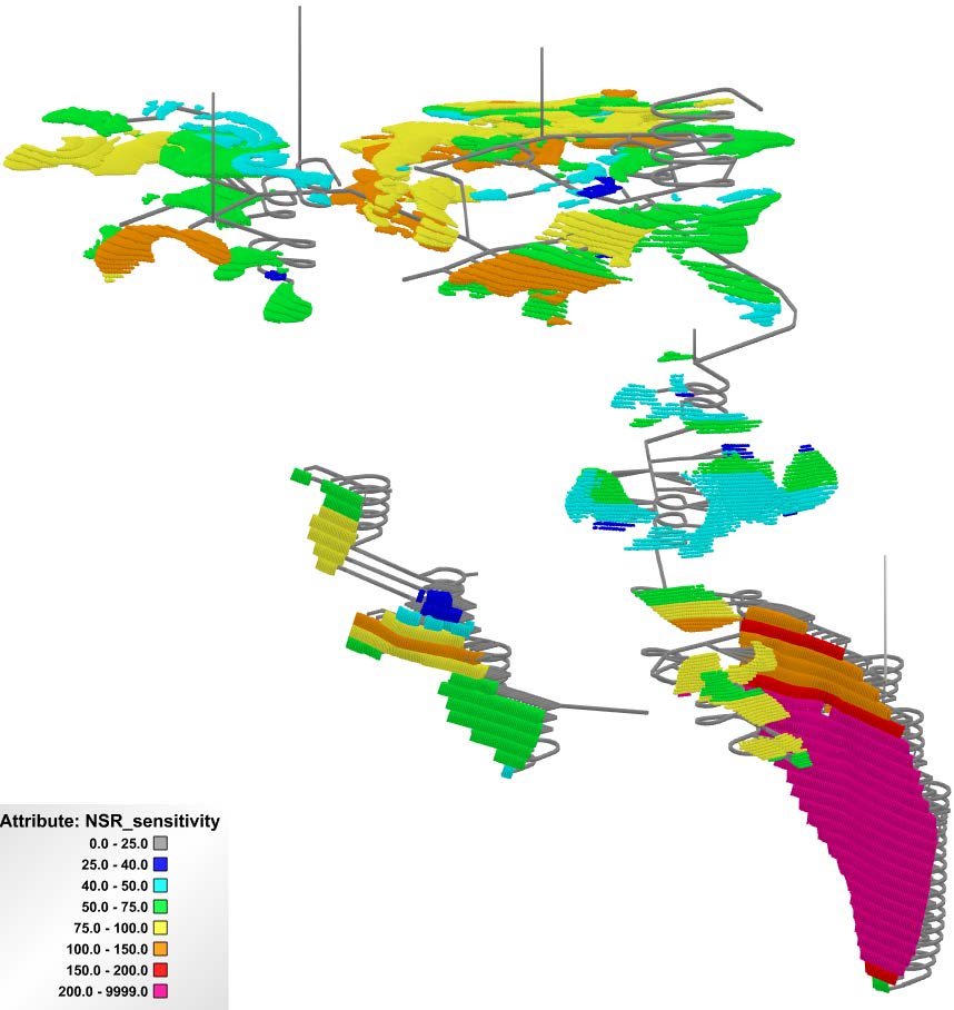
Figure 22-6: Mine Plan Resource colored by Sensitivity NSR (rotated view, looking Northeast)
22.6.2 Impact to Economics
The valuation of these alternate market assumptions is estimated to yield a net present value of US$106.1 million. The free cash flow project in this case presents three years of negative results, with cash flow becoming positive on the second year of commercial production. This also resulted in a longer payback period of around 3.15 years, compared to the base case payback period of 2.6 years. The lower zinc price is especially impactful in this case, as zinc is by far the highest revenue generator of the deposit, and this change reduced profits from every period modeled. The estimate of free cash flow of this alternate case is presented in Figure 22-6.
| 178 |
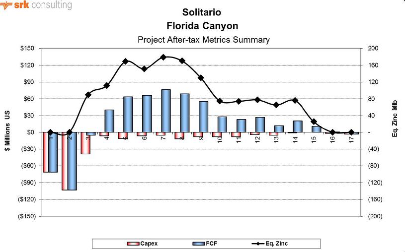
Source: SRK, 2017
Figure 22-7: Florida Canyon Alternate Case After-Tax FCF and Equivalent Metal Production
The indicative economic results of this alternate case are presented in Table 22-11, the table further evidences that zinc is responsible for the majority of the revenue generation, and the underground mining cost continues to be the heaviest cost center of the operation, followed by the mineral processing cost as a distant second.
| 179 |
Table 22-11: Florida Canyon Alternate Case Indicative Economic Results (Dry Basis)
| Description | Value | Units |
| Market Prices | ||
| Silver | 18.91 | US$/oz |
| Lead | 0.88 | US$/lb |
| Zinc | $1.06 | US$/lb |
| Estimate of Cash Flow (all values in US$000’s) | ||
| Concentrate Net Return | $/oz-Ag | |
| Silver Sales | $37,771 | $0.03 |
| Lead Sales | $137,603 | $0.10 |
| Zinc Sales | $1,481,158 | $1.06 |
| Total Revenue | $1,656,532 | $1.19 |
| Treatment, Smelting and Refining Charges | ($337,076) | |
| Freight, Impurities & Third Parties | ($96,935) | ($0.07) |
| Gross Revenue | $1,222,521 | |
| Royalties | ($42,624) | ($0.03) |
| Net Revenue | $1,179,897 | |
| Operating Costs | ||
| Open Pit Mining | $0 | $0.00 |
| Underground Mining | ($228,547) | ($0.16) |
| Process | ($144,063) | ($0.10) |
| G&A | ($39,153) | ($0.03) |
| Ordinary Rights | $0 | $0.00 |
| Total Operating | ($411,764) | ($0.29) |
| Operating Margin (EBITDA) | $768,133 | |
| Initial Capital | ($213,667) | |
| LoM Sustaining Capital | ($82,722) | |
| Income Tax | ($162,071) | |
| After Tax Free Cash Flow | $309,673 | |
| Payback | 3.15 | years |
| After-Tax IRR | 19.1% | |
| NPV @: 9% | $106,137 |
Source: SRK, 2017
| 180 |
Table 22-12 shows annual production and revenue forecasts for the life of mine of the alternate case.
Table 22-12: Florida Canyon Alternate Case LoM Annual Production and Revenues
|
Period |
RoM (Mt) |
Plant Feed (Mt) |
Lead Conc. (kt) |
Zinc Conc. (kt) |
Free Cash Flow (US$ millions) | Discounted Cash Flow (US$ millions) |
| -2 | 0.00 | 0.00 | 0.00 | 0.00 | (72) | (72) |
| -1 | 0.00 | 0.00 | 0.00 | 0.00 | (103) | (95) |
| 1 | 0.73 | 0.73 | 9.06 | 95.86 | (5) | (5) |
| 2 | 0.91 | 0.91 | 11.07 | 119.02 | 40 | 31 |
| 3 | 0.91 | 0.91 | 14.87 | 180.57 | 64 | 45 |
| 4 | 0.91 | 0.91 | 17.73 | 161.95 | 66 | 43 |
| 5 | 0.92 | 0.92 | 14.78 | 191.19 | 76 | 46 |
| 6 | 0.91 | 0.91 | 15.26 | 181.90 | 69 | 38 |
| 7 | 0.91 | 0.91 | 15.80 | 138.77 | 55 | 28 |
| 8 | 0.91 | 0.91 | 12.22 | 80.34 | 28 | 13 |
| 9 | 0.92 | 0.92 | 11.73 | 79.35 | 23 | 10 |
| 10 | 0.91 | 0.91 | 11.24 | 83.01 | 27 | 11 |
| 11 | 0.92 | 0.92 | 4.82 | 69.77 | 12 | 4 |
| 12 | 0.91 | 0.91 | 7.76 | 81.33 | 21 | 7 |
| 13 | 0.40 | 0.40 | 3.53 | 27.54 | 11 | 3 |
| 14 | 0.00 | 0.00 | 0.00 | 0.00 | 0 | 0 |
| 15 | 0.00 | 0.00 | 0.00 | 0.00 | (3) | (1) |
| Total | 11.19 | 11.19 | 150 | 1,491 | 310 | 106 |
Source: SRK, 2017
| 181 |
This change of metal prices in the alternate case economics, including the reduction of both zinc and lead and the raise of silver, does not significantly change the distribution of the revenue generation by metal. Figure 22-8 presents a very similar profile for each metal contribution compared to the base case.
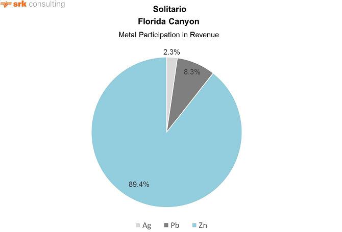
Source: SRK
Figure 22-8: Alternate Case Metal Participation in Revenue
The estimated all-in LoM cost decreased by US$0.01 to US$0.72/EqZn-lb as a result of reducing the royalty payments due to lower metal prices. Direct cash costs were raised by about US$0.01/EqZn-lb to a total of US$0.48/EqZn-lb due to the lower byproduct credit from the lower lead and silver price. Table 22-13 presents the details of the LoM cash costs.
| 182 |
Table 22-13: Florida Canyon Cash Costs
| Cash Costs | US$000's |
| Direct Cash Cost | |
| Underground Mining Cost | $228,547 |
| Process Cost | $144,063 |
| Site G&A Cost | $39,153 |
| Treatment Charges | $334,080 |
| Smelting & Refining Charges | $2,996 |
| Freight | $96,935 |
| By-Product Credits | ($175,374) |
| Direct Cash Costs | $670,401 |
| US$/t-ore | $59.93 |
| US$/lb-Zn | $0.48 |
| Indirect Cash Cost | |
| Royalties | $42,624 |
| Indirect Cash Costs | $42,624 |
| US$/t-ore | $3.81 |
| US$/lb-Zn | $0.03 |
| Direct + Indirect Cash Costs | $713,026 |
| US$/t-ore | $63.74 |
| US$/lb-Zn | $0.51 |
| Sustaining Capital Cash Cost | |
| Sustaining Capital | $82,722 |
| Sustaining Cash Costs | $82,722 |
| US$/t-ore | $7.39 |
| US$/lb-Zn | $0.06 |
| All-In Sustaining Cash Costs | $795,748 |
| US$/t-ore | $71.13 |
| US$/lb-Zn | $0.57 |
| Initial Capital Cash Cost | |
| Initial Capital | $213,667 |
| Initial Capital Cash Costs | $213,667 |
| US$/t-ore | $19.10 |
| US$/lb-Zn | $0.15 |
| All-In Cash Costs | $1,009,415 |
| US$/t-ore | $90.23 |
| US$/lb-Zn | $0.72 |
Source: SRK, 2017
This conservative metal price alternative has a significant effect on the economic results of the project in comparison with the base case, probably in a scale that it would warrant additional optimization of the mineable resources and project plan.
| 183 |
23 Adjacent Properties
There are no developed or advanced stage properties near the Project. The only historic commercial minerals undertaking was a short period of trial mining at Mina Grande 18 km northeast of the Property.
Minera Chambara controls the largest claim position within 30 km of the Property. Minera Chambara is a joint venture company between Votorantim and Solitario. These two companies and affiliates are title holders for the claims subject to this JV.
The only other publicly reported documentation related to mineral properties in the area is a NI 43-101 report filed by the company Rio Cristal (Brophy, 2012) pertaining to the Cristal property approximately 20 km to the north of the Property. This report does not include a Mineral Resource Statement. Rio Cristal no longer controls the claims considered in this report but the claims themselves remain in good standing held by individual claim owners.
| 184 |
24 Other Relevant Data and Information
SRK is unaware of any other information or explanation necessary to make the technical report understandable and not misleading.
| 185 |
25 Interpretation and Conclusions
| 25.1 | General |
The Florida Canyon Zinc Project is a significant greenfields potentially underground mineable high- grade zinc deposit containing associated lead and silver. The Project has a large land position and strong technical and financial backing through Solitario’s earn-in JV partner Votorantim. While this document represents the first formal economic evaluation of the Project, Votorantim and Cominco report having previously spent over US$60 million on drilling, test work and strategic planning for development (Solitario, 2014). Current projections in the zinc metal market suggest a near-term reduction in zinc supply as current major producers exhaust reserves.
SRK’s site visit to the project on the ground in northern Peru found it to be a well-organized facility, with current QA/QC protocols in place for drilling data verification and validation. Material handling, core storage and security were all at or above industry standards.
SRK used a number of methods to validate the Votorantim resource block model starting with a face-to-face meeting with the modeler and following on with a thorough audit of the model source data, geologic modeling techniques, grade and tonnage estimation methods and classification protocols. SRK found these to be in line with industry standards, having been produced with recognized mining software, defensible data and reasonable assumptions. SRK was able to independently validate the model results.
A significant component of the SRK input to this PEA was the development of the underground mine plan. Because Florida Canyon is a polymetallic zinc-lead-silver deposit, each model block in the mine model was evaluated on an NSR basis, which included an estimate of recovery. Recovery was developed from a robust 2014 metallurgical campaign that characterized all expected material types. A recovered grade by block was used to build the underground stoping plan, complete with access, ventilation and an assessment of mine recovery and dilution.
SRK is unaware of any environmental, permitting, legal, title, taxation or marketing factors that could limit or affect the resource stated in this document. The project will benefit from additional infill and exploration drilling, additional process-metallurgical test work, detailed engineering studies for infrastructure and tailings management and forward planning to clearly define concentrate transport and smelter costs.
| 25.2 | Mineral Resource Estimate |
The current exploration model for the Project has been applied successfully in drillhole planning and resource definition. There is low risk to the Project if no additional exploration is completed. However, additional drilling for resource definition has a strong potential to expand the known resource extent and upgrade Inferred resources to Measured and Indicated. The most prospective targets include:
| · | Extension drilling south of the San Jorge zone and northeast of the Karen-Milagros zones are considered the highest priority to increase high-grade zinc sulfide mineralization. Both zones are open in the recommended areas of drill testing. |
| · | Infill drilling several large un-drill tested areas surrounded by mineralized zones within the mineralized footprint has the potential to significantly increase resources. |
| · | Extension drilling peripheral to the currently defined mineralized footprint. |
| 186 |
| · | Further develop drill targets over the 20 km long northern Florida Canyon mineralized corridor where large areas of strong zinc in soil and rock chip geochemistry indicate the potential for additional mineralized zones. |
At present, the deposit is open laterally to the north and south as well as to the west and east on the downthrown sides of the horst that defines the limits of exploration to date. Gaps in the drill pattern within the footprint of the existing drilling provide another opportunity to increase resources where drill spacing limits the continuity of stratigraphically controlled mineralization. A constraint on effective exploration and delineation drilling in these areas is the access to drilling stations due to the rugged terrain. The completion of a road into the area will help to expedite future drilling and development programs by providing increased access and lowering costs. Additional drilling from underground is also under consideration.
The discovery of the high-angle, high-grade San Jorge zone has prompted more emphasis on angled drilling, where most of the historic drilling is vertical to near-vertical and is therefore ineffective at locating and defining near-vertical structures. These “break-through” structures have been mapped on surface in several locations, but due to logistical constraints, have not been adequately drill tested for their down-dip continuity. Similarly, there appear to be additional drill targets at the intersection of the high-angle structures and the flat manto zones, where grades are locally enhanced. These concentrations may be present within the existing drilling footprint, but require additional drilling to delineate. The high grade and potential tonnage of such targets provide an incentive to locate and further define resources of this geometry.
| 25.3 | Mineral Processing and Metallurgical Testing |
Processing of sulfide mineralization (zinc-lead-silver) from the Florida Canyon deposit is straight forward using conventional flotation to a concentrate followed by offsite smelting. Testwork indicates that producing a commercial quality zinc concentrate from mixed material needed to incorporate Dense Media Separation methods (DMS) in order to maintain high recoveries (80+%). However, a conventional flotation approach reached commercial quality (about 50%Zn) at the expense of lower metal recovery, with a similar outcome for the lead concentrate. It is SRK’s opinion that conventional flotation should be able to achieve enhanced commercial level results (grade and recovery) under improved crushing, grinding, and flotation conditions.
Available information about silver is very limited. The laboratory developed a relationship between lead's head grade and silver grade in the final lead concentrate. This relationship follows what is typically observed in this type of deposit, therefore as this stage of development it is assumed to be valid, but SRK recommends confirming it in the next testing phase of the project.
To optimize recovery and grade when attempting to reach separation of the zinc and lead minerals into their respective commercial quality concentrates, SRK recommends approaching the selection of samples for the next phase of metallurgical sampling and testing.
| · | The core logging needs to incorporate attributes like clay%, clay type, RQD, oxide content, sulfide content. |
| · | Assaying of the core should include whole rock analysis. |
| · | Collect samples for metallurgical testing representing distinctive zones in the deposit. Grade variability should be secondary criteria when selecting samples, but they must be reasonably close to what a potential mining operation would be able to deliver to the mill. |
| 187 |
| · | There are potential synergies for processing oxide mineralization at Florida Canyon using expertise that Votorantim has gained at the Vazante and Morro Agudo mines in Brazil. These other existing operations have experience recovering hemimorphite, smithsonite, and hydrozincite, which may improve future recovery projections for Florida Canyon. |
| 25.4 | Mineral Reserve Estimate |
There were no Mineral Reserves estimated for this PEA.
| 25.5 | Mining |
Using longhole stoping in steeply dipping areas, and cut and fill mining in flat lying areas of mineralization are seen as the appropriate mining methods for the deposit geometry, and both methods incorporate the use of tailings backfill. An NSR approach was used to calculate the value of a block and revenue for Pb, Zn, and Ag is considered. Stope optimization was completed to identify economic mining areas. The 3-D stope optimizer shapes and development design, along with dilution and mining recovery assumptions, are used to calculate tonnages and grades in the mine plan resource. A production schedule was generated using iGantt software targeting a production rate of 2,500 t/d (912,500 mineralized tonnes per year).
| 25.6 | Recovery Methods |
The Florida Canyon polymetallic zinc-lead-silver deposit can be processed using a conventional concentration plant consisting of three-stage crushing, grinding using ball mill, and differential flotation to produce two final products: a zinc concentrate and a lead concentrate. Detailed sizing and costing of the processing plant components will follow additional metallurgical testing proposed in this study. Power supply and water supply appear to be fairly well defined for the project, though additional studies may be needed to refine these services and the costs of these services to the project.
| 25.7 | Project Infrastructure |
The Florida Canyon deposit is located in steep terrain in a remote part of northern Peru with moderate to high rainfall. These geographic and climatic conditions pose challenges to both access and infrastructure development.
As presently understood, the key support services of power supply and water supply are available and part of a district-wide infrastructure improvement campaign being implemented by the Peruvian government and related third-party providers. The most significant advancement in the infrastructure investigation for the PEA was identifying the probability of hydroelectric power distribution to the site, as a lower cost alternative to on-site power generation. Water supply for operations appears to be straight forward, with abundant surface water available for mineral processing and camp support.
The infrastructure component with the largest footprint and projected cost is the tailings storage facility. As part of this study, SRK has evaluated this as a dry stack facility in order to achieve geotechnical stability and reduce the area requiring reclamation. Trade-off studies are warranted to optimize moisture content, binding characteristics, and compaction methods during tailings placement to minimize water infiltration.
| 188 |
| 25.8 | Environmental Studies and Permitting |
Additional environmental baseline studies are required for further project development.
Impact to groundwater is expected to be minimal as underground surface exposures are minor and future exposed sulfides are not acid generating. There are no groundwater wells required for processing or potable water supply. There will be little or no surface area disturbance related to waste rock placement.
Tailings are predicted to have low amounts of iron sulfide and to be geochemically stable with respect to acid rock drainage. There is also substantial neutralization capacity in the carbonate host rocks to mitigate acid generation. Residual lead and zinc sulfides have low acid-generating capacity; however, they are subject to metal leaching and therefore require compaction during placement.
SRK recommends in future studies to design the tailings surface and spillway stormwater structure and evaluate options to reduce or eliminate the long-term obligation for monitoring and maintenance.
| 25.9 | Capital and Operating Costs |
As part of the Florida Canyon valuation exercise, SRK prepared an estimate of both capital and operating costs associated with the designed mineable resources production schedule. All estimates were based on yearly inputs of physicals and all financial data is second quarter 2017 and currency is in U.S. dollars (US$), unless otherwise stated.
The total capital cost estimated for the Project was US$296 million, including US$213 million of initial capital and US$83 million of sustaining capital.
Capital costs for mining were based on a preliminary stoping plan for the Florida Canyon deposit complete with development, access and ventilation. The assessment resulted in an estimate of approximately US$76 million. The process plant cost estimate was based on data from similar flotation plants with the same capacity and same region. This investigation resulted in an estimate of about US$60 million. The cost associated with the required surface crushing and conveying was based on required distances and elevation gain to cover. These include the movement of material from three mine portals to the plant feed area and some waste material that will be used to build the embankment for the tailings storage facility. This investigation resulted in an estimate of around US$1.4 million. Offsite-infrastructure, site infrastructure, power supply, water supply and backfill infrastructure cost estimates were prepared based the required structures costs from comparable operations. It should be noted that this study assumes that a third party is planning to build a hydro power plant that will provide power to the project,
Operating costs for the life of mine are presented in Table 25-1.
Table 25-1: Florida Canyon Operating Costs Summary
| Description | LoM (US$000’s) | LoM (US$/t-Ore) | LoM (US$/lb-Zn) |
| Underground Mining | 228,547 | 20.43 | 0.16 |
| Process | 144,063 | 12.88 | 0.10 |
| G&A | 39,153 | 3.50 | 0.03 |
| Total Operating | 411,764 | 36.81 | 0.29 |
Source: SRK, 2017
| 189 |
Unit costs from similar projects in the same region or in the Americas, adjusted for labor and consumables differences, were used to estimate the LoM operating costs. All operating costs include supervision staff, operations labor, maintenance labor, consumables, electricity, fuels, lubricants, maintenance parts and any other operating expenditure identified by contributing engineers.
25.10 Economics
Florida Canyon is a zinc project, in which zinc contributes 90% to the overall revenue. Lead and silver are considered by-products of the operation. These metals contribute approximately 8% and 2% respectively.
Using the assumptions discussed in the previous sections, the Project is valuated at US$198 million. The Project’s all-in costs are estimated to be US$0.73/Zn-lb, on an equivalent production basis.
Underground mining costs are the most relevant direct costs of the operation, corresponding to approximately 56% to the on-site operating costs. Approximately 76% of the off-site costs are the treatment, smelting and refining charges.
The assumption of line power, compared to on-site power generation, makes significant positive impact to project economics. While there is sufficient confidence in the application of line power for it to be used as the base-case, there are some uncertainties regarding the timing of implementation of this component.
The high in situ grades of the zinc mineralization and low impurities in sulfides at Florida Canyon should generate a premium concentrate and a highly saleable product in a market where strong future demand is forecasted. The challenge to Project development lies in its remote location, which raises capital costs for construction and operating costs for concentrate delivery, among other things. Road access to the site is still under construction and is seen as a key component to Project advancement. High-relief terrain and high annual rainfall are conditions affecting development, especially in the area of infrastructure construction and process/tailings containment and stability.
Politically and socially, the development of a mining operation at this location is considered low risk as many of the local residents are already employed or seeking employment with Votorantim.
The Project seems to be most sensitive to fluctuations of the metal prices. The impact of exchange rate fluctuations was not evaluated, as all costs were estimated directly in US$. It is recommended that this information is updated in future evaluations to better estimate the impact of exchange rate fluctuations.
Even under distressed (-20%) metal prices the project will payback. Project break-even occurs when metal prices are reduced by about 32%.
The impact of actual net smelter terms and of impurities in the concentrates was not evaluated in this study. It is recommended that in the future a study of the Net Smelter Terms related to the Florida Canyon concentrates is conducted.
| 190 |
26 Recommendations
| 26.1 | Recommended Work Programs |
SRK acknowledges, after examination of the Project data set, that there have been a significant number of technical studies completed by Votorantim, many of which are beyond PEA level. Therefore, the work elements listed in Table 26-1 represent mostly prefeasibility and feasibility level engineering and drilling to support those studies.
At the juncture where prefeasibility level engineering has been completed, the Project will likely warrant further public reporting to an international standard (JORC, or NI 43-101). Technical information required to achieve this level of project development is described below. Costs for the recommended work are listed in Table 26-1.
26.1.1 Engineering Studies (Prefeasibility Level)
A Prefeasibility Study (PFS) for Florida Canyon requires additional metallurgical and geochemical test work as well as various detailed design improvements to refine costs. The key elements of the PFS are listed below.
| · | Mining methods, equipment selection and costs; |
| · | Mining dilution optimization and cost refinement; |
| · | Geotechnical testing and modeling: |
| o | Numerical modeling for underground mine stability and pillar definition; and |
| o | Modeling for facilities foundation stability. |
| · | Metallurgical testing: |
| o | Variability testing; |
| o | Flotation optimization; and |
| o | DMS characterization. |
| · | Processing trade-off studies; |
| · | Processing optimization and cost refinement; |
| · | Infrastructure design and costs: |
| o | Map and further quantify the condition of the existing roads and identify deficits and further design features (drainage/poor soil conditions) on the road system to optimize the location and number of roads for the project; |
| o | Develop a site-wide water balance to determine whether there is need to further develop surface water and ground water sources for makeup water; |
o Determine actual flow rates available from Tesoro Creek and confirm it as a water source; o Prepare a more detailed site-wide load estimate to determine a more detailed required power load and further develop the cost and timing of the third-party power supply option;
and
| o | Revisit the transportation study to optimize freight costs and to determine optimal market location and freight operating costs and capital costs. |
| · | Market studies for concentrate sales and treatment; |
| · | Hydrogeological characterization and modeling for water supply, permitting and water pollution control; |
| · | Geochemical characterization and modeling (waste rock and tailings); |
| 191 |
| · | Environmental baseline characterization; and |
| · | Technical Economic Modeling. |
26.1.2 Drilling
Drilling programs recommended by SRK will facilitate the modeling and trade-off studies planned at prefeasibility level. SRK also recommends drilling for resource expansion.
| · | Exploration targeting both known outcropping and new high-angle structures and structural intersections inside the current drilling footprint; |
| · | North and south step-out exploration on San Jorge structure (south) and K-M mantos (north); |
| · | Resource conversion core drilling (HQ): Inferred upgrade to Measured/Indicated in the resource (includes matrix-matched reference materials for QC); |
| · | Metallurgical drilling for flotation and comminution testing (PQ); |
| · | Geotechnical drilling and compressive strength testing to characterize ground conditions for underground mine planning; |
| · | Geotechnical characterization drilling for mill and tailings foundation stability; |
| · | Geotechnical drilling to provide stability analysis for tailings storage; and |
| · | Water supply definition and hydrogeological characterization for dewatering. |
26.1.3 Mining
Mining recommendations are as follows:
| · | Refine the underground mine plan with additional drilling; |
| · | Optimize the location of ramps/accesses and the order in which areas are mined; |
| · | Complete test work to determine the backfill material characteristics and placement options; |
| · | Geotechnical drilling and testing; and |
| · | Confirm productivities and operating cost assumptions based on detailed first principle’s buildup. |
| 26.2 | Work Program Costs |
Table 26-1 summarizes the costs for recommended work programs.
| 192 |
Table 26-1: Summary of Costs for Recommended Work
| Work Program | Estimated | Assumptions/Comments |
| Engineering Studies | Cost US$ | |
| Metallugical variability and recovery optimization test work | 500,000 | Commercial Laboratory |
| Prefeasibility Study (PFS) and Trade-off Studies | 600,000 | Votorantim or consultant engineer |
| Subtotal Studies | $1,100,000 | |
| Drilling | Salaried new hire or contract PM | |
| Exploration Drilling | 2,100,000 | 20 holes to 350 m at US$300/m |
| Resource Conversion Drilling | 2,100,000 | 20 holes to 350 m at US$300/m |
| Metallurgical Drilling for Flotation and Comminution | 1,225,000 | 10 PQ holes to 350 m at US$350/m |
| Geotechical Drilling for Mining | 500,000 | 10 holes oriented to 100 m at US$500/m |
| Geotechnical Drilling for Foundation Stability | 225,000 | 50 holes to 30 m at US$150/m |
| Hydrogeological Drilling | 600,000 | 4 holes to 300 m at US$500/m |
| Subtotal Drilling | $6,750,000 | |
| Studies + Drilling | 7,600,000 | |
| Contingency at 15% | 1,435,000 | |
| Total | $9,285,000 |
Source: SRK, 2017
| 193 |
| 27 | References |
ALS Minerals (2014a). Global Capability Statement 2014. Accessed 16 May 2014, from http://www.alsglobal.com/Our-Services/Minerals
ALS Minerals (2014b). ALS Geochemistry Schedule of Services and Fees 2014 (USD). Accessed 20 May, 2014, from http://www.alsglobal.com/en/Our-Services/Minerals/Geochemistry/Service- Schedule
AMEC (2013). Declaracion de Objectivo de Negocio para Proyecto Bongará (Scoping Study for the Bongará Project). 14 January 2013. 28 pages.
Barton, N.R., Lien, R., & Lunde, J. (1974). Engineering classification of rock masses for the design of tunnel support. Rock mechanics, 6(4), 189–236.Brophy, J.A. (2012). NI 43-101 Technical Report, Rio Cristal Resources Corp., Bongará Zinc Project. Effective date 31 January, 2012. 104 pages.
Bieniawski, Z.T. (1989) Engineering Rock Mass Classifications. Wiley, New York.
CIM (2014). Canadian Institute of Mining, Metallurgy and Petroleum Standards on Mineral Resources and Reserves: Definitions and Guidelines, May 10, 2014.
Carter, T.G. (2014) Guidelines for use of the Scaled Span Method for Surface Crown Pillar Stability Assessment. Ontario Ministry of Northern Development and Mines, 2010 pp 1-34.
Cominco (Perú) S.R.L. (2000). Bongará Project, Peru, 2000 Year-End Report, J.L.R. Muñoz and M.A. Tapia. 15 December, 2000. 55 pages.
Grimstad, E. & Barton, N (1993) Updating of the Q-System for NMT. Proc. Int. Conf. Sprayed Concrete- Modern Us of Wet Mix Sprayed Concrete for Underground Support, Fagernes (eds R. Kompen, O.A. Apsahl and K.R. Berg), 46-66. Norwegian Concrete Association, Oslo.
Guilbert, J.M. and Park, C.F., Jr. (1986). The Geology of Ore Deposits. Waveland Press, Inc., Long Grove, Illinois. 985 pages.
Hydro-Geo Consultores SAC (2010). Estudio hidrologico e hidrogeologico para sustentar el EIAsd del proyecto de exploracion minera Cañon Florida
Klohn Crippen Berger (2013). Geotechnical and Hydrological Investigations for the General Installations of the Bongará Project - Hydrogeological Characterization.
Klohn Crippen Berger (2013a). Investigaciones Geotécnicas e Hidrológicas para el Área de Instalaciones Generales. 101 pages.
Klohn Crippen Berger (2013b). Investigaciones Geotécnicas e Hidrológicas para el Área de Instalaciones Generales del Proyecto Bongará. Caracterización Geotécnica y Recomendaciones de Cimentación. 36 pages.
Potvin, Y. 1988. Empirical open stope design in Canada. The University of British Columbia, 1998.
p.350. (Ph.D. Thesis).Smallvill (2010). Tratamiento Metalurgico del Mineral de Bongará, Informe Final (Metallurgical Treatment of the Bongará [Sulfide] Ore, Final Report). April 2010. 89 pages.
| 194 |
Smallvill (2011a). Tratamiento Metalurgico del Mineral de Bongará Oxidos, Informe Final (Metallurgical Treatment of the Bongará Oxide Ore, Final Report). July 2011. 192 pages.
Smallvill (2011b). Tratamiento Metalurgico del Mineral de Bongará Mixtos, Informe Final (Metallurgical Treatment of the Bongará Mixed Ore, Final Report). August 2011. 202 pages.
Solitario (2014). Solitario Exploration and Royalty Corp. website. Accessed 09 June 2014, from http://www.solitarioresources.com/index.php
SRK Consulting (2014). Bongará Zinc Project Site Visit Notes, 10 May 2014. 19 pages including figures.
SRK Consulting (2014b). NI 43-101 Technical Report Mineral Resources Bongará Zinc Project. Prepared for Solitario Exploration and Royalty Corp. by SRK Consulting (U.S.) Inc. Effective Date June 05, 2014, Report Date, June 16, 2014, 145p.
Votorantim (2013a) Bongará Project Workshop, May 2013. Electronic slide presentation. 29 slides.
Votorantim (2013b). Mineral Resources Evaluation, Bongará Project, Amazonas Department, Peru. Prepared by Votorantim Metais Mineral Exploration and Mineral Resources Management Groups. December, 2013. 79 pages.
Votorantim (2014a). Informe Interno, Geología del Deposito Mississippi Valley Type Cañón Florida – Bongará, Bongará – Amazonas – Perú. (Internal Report, Geology of the Mississippi Valley Type Florida Canyon Deposit, Bongará Project, Bongará, Amazonas, Perú.) January 2014. 49 pages.
Votorantim (2014b). Informe Técnico, Muestreo y Análisis Químico, Proyecto Bongará. (Technical Report, Sampling and Chemical Analysis, Bongará Project.) 06 February 2014. 16 pages.
| 195 |
| 28 | Glossary |
The Mineral Resources and Mineral Reserves have been classified according to CIM (CIM, 2014). Accordingly, the Resources have been classified as Measured, Indicated or Inferred, the Reserves have been classified as Proven, and Probable based on the Measured and Indicated Resources as defined below.
| 28.1 | Mineral Resources |
A Mineral Resource is a concentration or occurrence of solid material of economic interest in or on the Earth’s crust in such form, grade or quality and quantity that there are reasonable prospects for eventual economic extraction. The location, quantity, grade or quality, continuity and other geological characteristics of a Mineral Resource are known, estimated or interpreted from specific geological evidence and knowledge, including sampling.
An Inferred Mineral Resource is that part of a Mineral Resource for which quantity and grade or quality are estimated on the basis of limited geological evidence and sampling. Geological evidence is sufficient to imply but not verify geological and grade or quality continuity. An Inferred Mineral Resource has a lower level of confidence than that applying to an Indicated Mineral Resource and must not be converted to a Mineral Reserve. It is reasonably expected that the majority of Inferred Mineral Resources could be upgraded to Indicated Mineral Resources with continued exploration.
An Indicated Mineral Resource is that part of a Mineral Resource for which quantity, grade or quality, densities, shape and physical characteristics are estimated with sufficient confidence to allow the application of Modifying Factors in sufficient detail to support mine planning and evaluation of the economic viability of the deposit. Geological evidence is derived from adequately detailed and reliable exploration, sampling and testing and is sufficient to assume geological and grade or quality continuity between points of observation. An Indicated Mineral Resource has a lower level of confidence than that applying to a Measured Mineral Resource and may only be converted to a Probable Mineral Reserve.
A Measured Mineral Resource is that part of a Mineral Resource for which quantity, grade or quality, densities, shape, and physical characteristics are estimated with confidence sufficient to allow the application of Modifying Factors to support detailed mine planning and final evaluation of the economic viability of the deposit. Geological evidence is derived from detailed and reliable exploration, sampling and testing and is sufficient to confirm geological and grade or quality continuity between points of observation. A Measured Mineral Resource has a higher level of confidence than that applying to either an Indicated Mineral Resource or an Inferred Mineral Resource. It may be converted to a Proven Mineral Reserve or to a Probable Mineral Reserve.
| 28.2 | Mineral Reserves |
A Mineral Reserve is the economically mineable part of a Measured and/or Indicated Mineral Resource. It includes diluting materials and allowances for losses, which may occur when the material is mined or extracted and is defined by studies at prefeasibility or feasibility level as appropriate that include application of modifying factors. Such studies demonstrate that, at the time of reporting, extraction could reasonably be justified.
| 196 |
The reference point at which Mineral Reserves are defined, usually the point where the ore is delivered to the processing plant, must be stated. It is important that, in all situations where the reference point is different, such as for a saleable product, a clarifying statement is included to ensure that the reader is fully informed as to what is being reported. The public disclosure of a Mineral Reserve must be demonstrated by a prefeasibility study or feasibility study.
A Probable Mineral Reserve is the economically mineable part of an Indicated, and in some circumstances, a Measured Mineral Resource. The confidence in the Modifying Factors applying to a Probable Mineral Reserve is lower than that applying to a Proven Mineral Reserve.
A Proven Mineral Reserve is the economically mineable part of a Measured Mineral Resource. A Proven Mineral Reserve implies a high degree of confidence in the Modifying Factors.
| 28.3 | Definition of Terms |
The following general mining terms may be used in this report.
Table 28-1: Definition of Terms
| Term | Definition |
| Assay | The chemical analysis of mineral samples to determine the metal content. |
| Capital Expenditure | All other expenditures not classified as operating costs. |
| Composite | Combining more than one sample result to give an average result over a larger distance. |
| Concentrate | A metal-rich product resulting from a mineral enrichment process such as gravity concentration or flotation, in which most of the desired mineral has been separated from the waste material in the ore. |
| Crushing | Initial process of reducing ore particle size to render it more amenable for further processing. |
| Cut-off Grade (CoG) | The grade of mineralized rock, which determines as to whether or not it is economic to recover its gold content by further concentration. |
| Dilution | Waste, which is unavoidably mined with ore. |
| Dip | Angle of inclination of a geological feature/rock from the horizontal. |
| Fault | The surface of a fracture along which movement has occurred. |
| Footwall | The underlying side of an orebody or stope. |
| Gangue | Non-valuable components of the ore. |
| Grade | The measure of concentration of gold within mineralized rock. |
| Hangingwall | The overlying side of an orebody or slope. |
| Haulage | A horizontal underground excavation which is used to transport mined ore. |
| Hydrocyclone | A process whereby material is graded according to size by exploiting centrifugal forces of particulate materials. |
| Igneous | Primary crystalline rock formed by the solidification of magma. |
| Kriging | An interpolation method of assigning values from samples to blocks that minimizes the estimation error. |
| Level | Horizontal tunnel the primary purpose is the transportation of personnel and materials. |
| Lithological | Geological description pertaining to different rock types. |
| LoM Plans | Life-of-Mine plans. |
| LRP | Long Range Plan. |
| Material Properties | Mine properties. |
| Milling | A general term used to describe the process in which the ore is crushed and ground and subjected to physical or chemical treatment to extract the valuable metals to a concentrate or finished product. |
| Mineral/Mining Lease | A lease area for which mineral rights are held. |
| Mining Assets | The Material Properties and Significant Exploration Properties. |
| Ongoing Capital | Capital estimates of a routine nature, which is necessary for sustaining operations. |
| Ore Reserve | See Mineral Reserve. |
| 197 |
| Term | Definition |
| Pillar | Rock left behind to help support the excavations in an underground mine. |
| RoM | Run-of-Mine. |
| Sedimentary | Pertaining to rocks formed by the accumulation of sediments, formed by the erosion of other rocks. |
| Shaft | An opening cut downwards from the surface for transporting personnel, equipment, supplies, ore and waste. |
| Sill | A thin, tabular, horizontal to sub-horizontal body of igneous rock formed by the injection of magma into planar zones of weakness. |
| Smelting | A high temperature pyrometallurgical operation conducted in a furnace, in which the valuable metal is collected to a molten matte or doré phase and separated from the gangue components that accumulate in a less dense molten slag phase. |
| Stope | Underground void created by mining. |
| Stratigraphy | The study of stratified rocks in terms of time and space. |
| Strike | Direction of line formed by the intersection of strata surfaces with the horizontal plane, always perpendicular to the dip direction. |
| Sulfide | A sulfur bearing mineral. |
| Tailings | Finely ground waste rock from which valuable minerals or metals have been extracted. |
| Thickening | The process of concentrating solid particles in suspension. |
| Total Expenditure | All expenditures including those of an operating and capital nature. |
| Variogram | A statistical representation of the characteristics (usually grade). |
| 28.4 | Abbreviations |
The following abbreviations may be used in this report.
Table 28-2: Abbreviations
| Abbreviation | Unit or Term |
| A | ampere |
| AA | atomic absorption |
| A/m2 | amperes per square meter |
| ANFO | ammonium nitrate fuel oil |
| Ag | silver |
| Au | gold |
| AuEq | gold equivalent grade |
| °C | degrees Centigrade |
| CCD | counter-current decantation |
| CIL | carbon-in-leach |
| CoG | cut-off grade |
| cm | centimeter |
| cm2 | square centimeter |
| cm3 | cubic centimeter |
| cfm | cubic feet per minute |
| ConfC | confidence code |
| CRec | core recovery |
| CSS | closed-side setting |
| CTW | calculated true width |
| ° | degree (degrees) |
| dia. | diameter |
| EIS | Environmental Impact Statement |
| EMP | Environmental Management Plan |
| FA | fire assay |
| ft | foot (feet) |
| ft2 | square foot (feet) |
| ft3 | cubic foot (feet) |
| g | gram |
| 198 |
| Abbreviation | Unit or Term |
| gal | gallon |
| g/L | gram per liter |
| g-mol | gram-mole |
| gpm | gallons per minute |
| g/t | grams per tonne |
| ha | hectares |
| HDPE | Height Density Polyethylene |
| hp | horsepower |
| HTW | horizontal true width |
| ICP | induced couple plasma |
| ID2 | inverse-distance squared |
| ID3 | inverse-distance cubed |
| IFC | International Finance Corporation |
| ILS | Intermediate Leach Solution |
| kA | kiloamperes |
| kg | kilograms |
| km | kilometer |
| km2 | square kilometer |
| koz | thousand troy ounce |
| kt | thousand tonnes |
| kt/d | thousand tonnes per day |
| kt/y | thousand tonnes per year |
| kV | kilovolt |
| kW | kilowatt |
| kWh | kilowatt-hour |
| kWh/t | kilowatt-hour per metric tonne |
| L | liter |
| L/sec | liters per second |
| L/sec/m | liters per second per meter |
| lb | pound |
| LHD | Long-Haul Dump truck |
| LLDDP | Linear Low Density Polyethylene Plastic |
| LOI | Loss On Ignition |
| LoM | Life-of-Mine |
| m | meter |
| m2 | square meter |
| m3 | cubic meter |
| masl | meters above sea level |
| MARN | Ministry of the Environment and Natural Resources |
| MDA | Mine Development Associates |
| mg/L | milligrams/liter |
| mm | millimeter |
| mm2 | square millimeter |
| mm3 | cubic millimeter |
| MME | Mine & Mill Engineering |
| Mlb | million pounds |
| Moz | million troy ounces |
| Mt | million tonnes |
| MTW | measured true width |
| MW | million watts |
| m.y. | million years |
| NGO | non-governmental organization |
| NI 43-101 | Canadian National Instrument 43-101 |
| OSC | Ontario Securities Commission |
| oz | troy ounce |
| % | percent |
| PLC | Programmable Logic Controller |
| PLS | Pregnant Leach Solution |
| PMF | probable maximum flood |
| 199 |
| Abbreviation | Unit or Term |
| ppb | parts per billion |
| ppm | parts per million |
| QA/QC | Quality Assurance/Quality Control |
| RC | rotary circulation drilling |
| RoM | Run-of-Mine |
| RQD | Rock Quality Description |
| SEC | U.S. Securities & Exchange Commission |
| sec | second |
| SG | specific gravity |
| SPT | standard penetration testing |
| st | short ton (2,000 pounds) |
| t | tonne (metric ton) (2,204.6 pounds) |
| t/h | tonnes per hour |
| t/d | tonnes per day |
| t/y | tonnes per year |
| TSF | tailings storage facility |
| TSP | total suspended particulates |
| µm | micron or microns |
| V | volts |
| VFD | variable frequency drive |
| W | watt |
| XRD | x-ray diffraction |
| y | year |
| 200 |
Appendices
| 201 |
Appendix A: Certificates of Qualified Persons
| 202 |
CERTIFICATE OF AUTHOR
I, Walter Hunt, B.Sc. M. Sc., C.P.G do hereby certify that:
| 1. | I am Chief Operating Officer of Solitario Zinc Corp, 4251 Kipling St. Ste. 390, Wheat Ridge CO, USA. |
| 2. | This certificate applies to the technical report titled “NI 43-101 Technical Report, Preliminary Economic Assessment, Florida Canyon Zinc Project, Amazonas Department, Peru” with an Effective Date of July 13, 2017 (the “Technical Report”). |
I graduated with a degree in Bachelor of Science from Furman University in 1974. In addition, I have obtained a Master of Engineering from Colorado School of Mines in 1980. I am a Certified Professional Geologist through membership in the American Institute of Professional Geologists, CPG-11550.
| 3. | I have worked as a Geologist for a total of 40 years since my graduation from university. My relevant experience includes as an independent contract geologist and as Geologist for Conoco Minerals, Anaconda Exploration and Noranda Exploration, as a Senior Geologist for American Gold Minerals Corp (1976-1986), as Senior Geologist, Chief Geologist and Superintendent of Technical Services for Echo Bay Mines (1986-1994), as Vice President, Exploration and as President, South America Operations for Crown Resources and Solitario Resources, (1994-2008), Solitario Resources and as Chief Operating Officer, Solitario Resources, Solitario Exploration and Royalty Corp and Solitario Zinc Corp (2008- present). |
| 4. | I have read the definition of “qualified person” set out in National Instrument 43-101 (NI 43-101) and certify that by reason of my education, affiliation with a professional association (as defined in NI 43-101) and past relevant work experience, I fulfill the requirements to be a “qualified person” for the purposes of NI 43-101. |
| 5. | I supervised exploration work on the Bongará Property from 1994 to 1996 and have acted as owner representative to joint venture work from 1996 to present. |
| 6. | I am responsible for the preparation of Sections 2, 4, and portions of 20 summarized therefrom, of this Technical Report. |
| 7. | I am not independent of the issuer and have been employed by the issuer since 1994. |
| 8. | I have had prior involvement with the property that is the subject of the Technical Report. The nature of my prior involvement is as an employee of Solitario Resources Corp and as joint venture representative of Solitario Resources and Solitario Exploration Corp. |
| 9. | I have read NI 43-101 and Form 43-101-F1 and the sections of the Technical Report I am responsible for have been prepared in compliance with that instrument and form. |
| 10. | As of the aforementioned Effective Date, to the best of my knowledge, information and belief, the sections of the Technical Report I am responsible for contains all scientific and technical information that is required to be disclosed to make the Technical Report not misleading. |
Dated this 3rd Day of August, 2017 “signed”
_ Walter Hunt, B.Sc. M. Sc., C.P.G
| 203 |
CERTIFICATE OF QUALIFIED PERSON
I, J.B. Pennington, M.Sc., C.P.G., do hereby certify that:
| 1. | I am Principal Mining Geologist of SRK Consulting (U.S.), Inc., 5250 Neil Road, Suite 300, Reno, Nevada 89502. |
| 2. | This certificate applies to the technical report titled “NI 43-101 Technical Report, Preliminary Economic Assessment, Florida Canyon Zinc Project, Amazonas Department, Peru” with an Effective Date of July 13, 2017 (the “Technical Report”). |
| 3. | I graduated with a Bachelor of Science Degree in Geology from Tulane University, New Orleans, La., USA; May 1985; and a Master of Science Degree in Geology from Tulane University, New Orleans, La., USA; May 1987. I am a Certified Professional Geologist through membership in the American Institute of Professional Geologists, C.P.G. #11245. I have been employed as a geologist in the mining and mineral exploration business, continuously, for the past 30 years, since my undergraduate graduation from university. My relevant experience for the purpose of the Technical Report is: |
| · | Project Geologist, Archaen gold exploration with Freeport-McMoRan Australia Ltd. Perth Australia, 1987-1989; |
| · | Exploration Geologist, polymetallic regional exploration, Freeport-McMoRan Inc; Papua, Indonesia, 1990-1994; |
| · | Chief Mine Geologist, mine geology and resource estimation, Grasberg Cu-Au Deposit, Freeport- McMoRan Inc, Papua, Indonesia 1995-1998; |
| · | Corporate Strategic Planning: Geology and Resources, Freeport-McMoRan Inc., New Orleans, LA., 1999; |
| · | Independent Consultant: Geology, Steamboat Springs, CO., 2000; |
| · | Senior Geologist, environmental geology and mine closure, MWH Consulting, Inc., Steamboat Springs, CO., 2000-2003; |
| · | Principal Mining Geologist, precious and base metal exploration, resource modeling, and mine development, SRK Consulting (U.S.), Inc., 2004 to present; |
| · | Experience in the above positions working with, reviewing and conducting resource estimation and feasibility studies in concert with mining and process engineers; and |
| · | As a consultant, I have participated in the preparation of NI 43-101 Technical reports from 2006-to present. |
| 4. | I have read the definition of “qualified person” set out in National Instrument 43-101 (NI 43-101) and certify that by reason of my education, affiliation with a professional association (as defined in NI 43-101) and past relevant work experience, I fulfill the requirements to be a “qualified person” for the purposes of NI 43-101. |
| 5. | I have not visited the Florida Canyon property. |
| 6. | I am responsible for the preparation of Sections 5, 6, 7, 8, 9, 10, 12, 14, 23, 24, and portions of 1, 20, 25, and 26 summarized therefrom, of this Technical Report. |
| 7. | I am independent of the issuer applying all of the tests in section 1.5 of NI 43-101. |
| 8. | I have had prior involvement with the property that is the subject of the Technical Report. The nature of my prior involvement is co-author and Qualified Person for the NI 43-101 Technical Report on Resources, Bongará Zinc Project, effective date June 5, 2014. |
U.S. Offices:
Canadian Offices:
Group Offices:
| Anchorage | 907.677.3520 | Saskatoon | 306.955.4778 | Africa |
| Clovis | 559.452.0182 | Sudbury | 705.682.3270 | Asia |
| Denver | 303.985.1333 | Toronto | 416.601.1445 | Australia |
| Elko | 775.753.4151 | Vancouver | 604.681.4196 | Europe |
| Fort Collins | 970.407.8302 | Yellowknife | 867.873.8670 | North America |
| Reno | 775.828.6800 | South America | ||
| Tucson | 520.544.3688 |
| 204 |
SRK Consulting (U.S.), Inc. Page 2
| 9. | I have read NI 43-101 and Form 43-101F1 and the sections of the Technical Report I am responsible for have been prepared in compliance with that instrument and form. |
| 10. | As of the aforementioned Effective Date, to the best of my knowledge, information and belief, the sections of the Technical Report I am responsible for contains all scientific and technical information that is required to be disclosed to make the Technical Report not misleading. |
Dated this 3rd Day of August, 2017.
“signed”
_
J.B. Pennington, M.Sc., C.P.G. [#11245]
QP_Cert_Pennington_20170802
| 205 |
CERTIFICATE OF QUALIFIED PERSON
I, Joanna Poeck, BEng Mining, SME-RM, MMSAQP, do hereby certify that:
| 1. | I am a Senior Mining Engineer of SRK Consulting (U.S.), Inc., 1125 Seventeenth Street, Suite 600, Denver, CO, USA, 80202. |
| 2. | This certificate applies to the technical report titled “NI 43-101 Technical Report, Preliminary Economic Assessment, Florida Canyon Zinc Project, Amazonas Department, Peru” with an Effective Date of July 13, 2017 (the “Technical Report”). |
| 3. | I graduated with a degree in Mining Engineering from Colorado School of Mines in 2003. I am a Registered Member of the Society of Mining, Metallurgy & Exploration Geology. I am a QP member of the Mining & Metallurgical Society of America. I have worked as a Mining Engineer for a total of 14 years since my graduation from university. My relevant experience includes open pit and underground design, mine scheduling, pit optimization and truck productivity analysis. |
| 4. | I have read the definition of “qualified person” set out in National Instrument 43-101 (NI 43-101) and certify that by reason of my education, affiliation with a professional association (as defined in NI 43-101) and past relevant work experience, I fulfill the requirements to be a “qualified person” for the purposes of NI 43-101. |
| 5. | I have not visited the Florida Canyon Zinc property. |
| 6. | I am responsible for the preparation of Sections 15, 16.1, 16.3, 16.4, 16.5 and portions of 1, 25 and 26 summarized therefrom, of this Technical Report. |
| 7. | I am independent of the issuer applying all of the tests in section 1.5 of NI 43-101. |
| 8. | I have not had prior involvement with the property that is the subject of the Technical Report. |
| 9. | I have read NI 43-101 and Form 43-101F1 and the sections of the Technical Report I am responsible for have been prepared in compliance with that instrument and form. |
| 10. | As of the aforementioned Effective Date, to the best of my knowledge, information and belief, the sections of the Technical Report I am responsible for contains all scientific and technical information that is required to be disclosed to make the Technical Report not misleading. |
Dated this 3rd Day of August, 2017.
“signed”
_
Joanna Poeck, BEng Mining, SME-RM [#4131289RM], MMSAQP [#01387QP]
U.S. Offices:
Canadian Offices:
Group Offices:
| Anchorage | 907.677.3520 | Saskatoon | 306.955.4778 | Africa |
| Clovis | 559.452.0182 | Sudbury | 705.682.3270 | Asia |
| Denver | 303.985.1333 | Toronto | 416.601.1445 | Australia |
| Elko | 775.753.4151 | Vancouver | 604.681.4196 | Europe |
| Fort Collins | 970.407.8302 | Yellowknife | 867.873.8670 | North America |
| Reno | 775.828.6800 | South America | ||
| Tucson | 520.544.3688 |
| 206 |
SRK Consulting (U.S.), Inc. Suite 600
1125 Seventeenth Street
Denver, CO 80202
T: 303.985.1333
F: 303.985.9947
denver@srk.com www.srk.com
CERTIFICATE OF QUALIFIED PERSON
I, Jeff Osborn, BEng Mining, MMSAQP do hereby certify that:
| 1. | I am a Principal Consultant (Mining Engineer) of SRK Consulting (U.S.), Inc., 1125 Seventeenth, Suite 600, Denver, CO, USA, 80202. |
| 2. | This certificate applies to the technical report titled “NI 43-101 Technical Report, Preliminary Economic Assessment, Florida Canyon Zinc Project, Amazonas Department, Peru” with an Effective Date of July 13, 2017 (the “Technical Report”). |
| 3. | I graduated with a Bachelor of Science Mining Engineering degree from the Colorado School of Mines in 1986. I am a Qualified Professional (QP) Member of the Mining and Metallurgical Society of America. I have worked as a Mining Engineer for a total of 29 years since my graduation from university. My relevant experience includes responsibilities in operations, maintenance, engineering, management, and construction activities. |
| 4. | I have read the definition of “qualified person” set out in National Instrument 43-101 (NI 43-101) and certify that by reason of my education, affiliation with a professional association (as defined in NI 43-101) and past relevant work experience, I fulfill the requirements to be a “qualified person” for the purposes of NI 43-101. |
| 5. | I have not visited the Florida Canyon Zinc Property. |
| 6. | I am responsible for the preparation of Sections 18, 19, 21, 22, and portions of 1, 25 and 26 summarized therefrom of this Technical Report. |
| 7. | I am independent of the issuer applying all of the tests in section 1.5 of NI 43-101. I have not had prior involvement with the property that is the subject of the Technical Report. |
| 8. | I have read NI 43-101 and Form 43-101F1 and the sections of the Technical Report I am responsible for have been prepared in compliance with that instrument and form. |
| 9. | As of the aforementioned Effective Date, to the best of my knowledge, information and belief, the sections of the Technical Report I am responsible for contains all scientific and technical information that is required to be disclosed to make the Technical Report not misleading. |
Dated this 3rd Day of August, 2017.
“signed”
_ Jeff Osborn, BEng Mining, MMSAQP [#01458QP]
| 207 |
CERTIFICATE OF QUALIFIED PERSON
I, Daniel H. Sepulveda, B.Sc, SME-RM, do hereby certify that:
| 1. | I am Associate Consultant (Metallurgy) of SRK Consulting (U.S.), Inc., 1125 Seventeenth Street, Suite 600, Denver, CO, USA, 80202. |
| 2. | This certificate applies to the technical report titled “NI 43-101 Technical Report, Preliminary Economic Assessment, Florida Canyon Zinc Project, Amazonas Department, Peru” with an Effective Date of July 13, 2017 (the “Technical Report”). |
| 3. | I graduated with a degree in Extractive Metallurgy from University of Chile in 1992. I am a registered member of the Society of Mining, Metallurgy, and Exploration, Inc. (SME), member No 4206787RM. I have worked as a Metallurgist for a total of 25 years since my graduation from university. My relevant experience includes: employee of several mining companies, engineering & construction companies, and as a consulting engineer. |
| 4. | I have read the definition of “qualified person” set out in National Instrument 43-101 (NI 43-101) and certify that by reason of my education, affiliation with a professional association (as defined in NI 43-101) and past relevant work experience, I fulfill the requirements to be a “qualified person” for the purposes of NI 43-101. |
| 5. | I have not visited the Florida Canyon site |
| 6. | I am responsible for the preparation of Sections 13, 17, the capital and operating cost for processing in Section 21, and portions of 1, 25 and 26 summarized therefrom, of this Technical Report. |
| 7. | I am independent of the issuer applying all of the tests in section 1.5 of NI 43-101. |
| 8. | I have not had prior involvement with the property that is the subject of the Technical Report. |
| 9. | I have read NI 43-101 and Form 43-101F1 and the sections of the Technical Report I am responsible for have been prepared in compliance with that instrument and form. |
| 10. | As of the aforementioned Effective Date, to the best of my knowledge, information and belief, the sections of the Technical Report I am responsible for contains all scientific and technical information that is required to be disclosed to make the Technical Report not misleading. |
Dated this 3rd Day of August, 2017.
“signed”
_ Daniel H. Sepulveda, B.Sc, SME-RM
U.S. Offices:
Canadian Offices:
Group Offices:
| Anchorage | 907.677.3520 | Saskatoon | 306.955.4778 | Africa |
| Clovis | 559.452.0182 | Sudbury | 705.682.3270 | Asia |
| Denver | 303.985.1333 | Toronto | 416.601.1445 | Australia |
| Elko | 775.753.4151 | Vancouver | 604.681.4196 | Europe |
| Fort Collins | 970.407.8302 | Yellowknife | 867.873.8670 | North America |
| Reno | 775.828.6800 | South America |
| 208 |
SRK Exploration Services 12 St. Andrews Crescent, Cardiff, CF10 3DD Wales, UK
T: +44 2920 233 233
F:
+44 2920 233 211
www.srk.com
CERTIFICATE OF QUALIFIED PERSON
I, James Gilbertson, Chartered Geologist, do hereby certify that:
| 1. | I am a Principal Exploration Geologist of SRK Exploration Services, 12 St. Andrews Crescent, Cardiff, CF10 3DD, Wales, UK. |
| 2. | This certificate applies to the technical report titled “NI 43-101 Technical Report, Preliminary Economic Assessment, Florida Canyon Zinc Project, Amazonas Department, Peru” with an Effective Date of July 13, 2017 (the “Technical Report”). |
| 3. | I graduated with a degree in Geology from Durham University in 2000. In addition, I have obtained a Masters in Mining Geology from Camborne School of Mines in 2002. I am a Chartered Geologist of the Geological Society of London. I have worked as a Geologist for a total of 17 years since my graduation from university. My relevant experience includes exploration planning, mineral project auditing, mineral resource estimation and project due diligence on a verity of commodities and deposit style globally. |
| 4. | I have read the definition of “qualified person” set out in National Instrument 43-101 (NI 43-101) and certify that by reason of my education, affiliation with a professional association (as defined in NI 43-101) and past relevant work experience, I fulfill the requirements to be a “qualified person” for the purposes of NI 43-101. |
| 5. | I visited the Florida Canyon property on May 5, 2014 for three days. |
| 6. | I am responsible for the preparation of Section 11, the site visit, inspection of geological sampling and data collection practices, and review of resource estimation practices of the Technical Report. |
| 7. | I am independent of the issuer applying all of the tests in section 1.5 of NI 43-101. |
| 8. | I have had prior involvement with the property that is the subject of the Technical Report. The nature of my prior involvement is as an independent consultant during the 2014 Mineral Resource estimate. |
| 9. | I have read NI 43-101 and Form 43-101F1 and the sections of the Technical Report I am responsible for have been prepared in compliance with that instrument and form. |
| 10. | As of the aforementioned Effective Date, to the best of my knowledge, information and belief, the sections of the Technical Report I am responsible for contains all scientific and technical information that is required to be disclosed to make the Technical Report not misleading. |
Dated this 3rd Day of August, 2017.
“signed”
_ James Gilbertson, Professional Chartered Geologist
| 209 |
CERTIFICATE OF QUALIFIED PERSON
I, John Tinucci, Ph.D., P.E., ISRM do hereby certify that:
| 1. | I am a Principal Geotechnical Mining Engineer of SRK Consulting (U.S.), Inc., 1125 Seventeenth Street, Suite 600, Denver, CO, USA, 80202. |
| 2. | This certificate applies to the technical report titled “NI 43-101 Technical Report, Preliminary Economic Assessment, Florida Canyon Zinc Project, Amazonas Department, Peru” with an Effective Date of July 13, 2017 (the “Technical Report”). |
| 3. | I graduated with a degree in B.S. in Civil Engineering from Colorado State University, in 1980. In addition, I have obtained a M.S. in Geotechnical Engineering from University of California, Berkeley, in 1983 and I have obtained a Ph.D. in Geotechnical Engineering, Rock Mechanics from the University of California, Berkeley in 1985. I am member of the American Rock Mechanics Association, a member of the International Society of Rock Mechanics, a member of the ASCE GeoInstitute, and a Registered Member of the Society for Mining, Metallurgy & Exploration. I have worked as a Mining and Geotechnical Engineer for a total of 37 years since my graduation from university. My relevant experience includes 34 years of professional experience. I have 15 years managerial experience leading project teams, managing P&L operations for 120 staff, and directed own company of 8 staff for 8 years. I have technical experience in mine design, prefeasibility studies, feasibility studies, geomechanical assessments, rock mass characterization, project management, numerical analyses, underground mine stability, subsidence, tunneling, ground support, slope design and stabilization, excavation remediation, induced seismicity and dynamic ground motion. My industry commodities experience includes salt, potash, coal, platinum/palladium, iron, molybdenum, gold, silver, zinc, diamonds, and copper. My mine design experience includes open pit, room and pillar, (single and multi-level), conventional drill-and-blast and mechanized cutting, longwall, steep narrow vein, cut and fill, block caving, sublevel caving and cut and fill longhole stoping and paste backfilling |
| 4. | I have read the definition of “qualified person” set out in National Instrument 43-101 (NI 43-101) and certify that by reason of my education, affiliation with a professional association (as defined in NI 43-101) and past relevant work experience, I fulfill the requirements to be a “qualified person” for the purposes of NI 43-101. |
| 5. | I have not visited the Florida Canyon property. |
| 6. | I am responsible for the preparation of Section 16.2 of the Technical Report. |
| 7. | I am independent of the issuer applying all of the tests in section 1.5 of NI 43-101. |
| 8. | I have not had prior involvement with the property that is the subject of the Technical Report. |
| 9. | I have read NI 43-101 and Form 43-101F1 and the sections of the Technical Report I am responsible for have been prepared in compliance with that instrument and form. |
| 10. | As of the aforementioned Effective Date, to the best of my knowledge, information and belief, the sections of the Technical Report I am responsible for contains all scientific and technical information that is required to be disclosed to make the Technical Report not misleading. |
U.S. Offices:
Canadian Offices:
Group Offices:
| Anchorage | 907.677.3520 | Saskatoon | 306.955.4778 | Africa |
| Clovis | 559.452.0182 | Sudbury | 705.682.3270 | Asia |
| Denver | 303.985.1333 | Toronto | 416.601.1445 | Australia |
| Elko | 775.753.4151 | Vancouver | 604.681.4196 | Europe |
| Fort Collins | 970.407.8302 | Yellowknife | 867.873.8670 | North America |
| Reno | 775.828.6800 | South America |
| 210 |
SRK Consulting (U.S.), Inc. Page 2
Dated this 3rd Day of August, 2017.
“signed”
_ John Tinucci, Ph.D., P.E., ISRM
QP_Cert-Tinucci_20170803-signed