Attached files
Exhibit 10.1
|
[BAR CODE]
|
|
|
US008169115B1
|
|
(12)
|
United States Patent
|
(10)
|
Patent No.:
|
US 8,169,115 B1
|
||||||
|
Monfort
|
(45)
|
Date of Patent:
|
May 1, 2012
|
|||||||
|
(54)
|
MOTOR DISTRIBUTOR SYSTEM
|
4,531,072 A *
|
7/1985
|
Weaver et al. ......... 310/162
|
||||||
|
4,635,489 A *
|
111987
|
Imamura et al. .......... 74/7 E
|
||||||||
|
4,654,577 A *
|
3/1987
|
Howard .................. 322/28
|
||||||||
|
4,891,996 A *
|
111990
|
Isozumi et al. ............. 74/6
|
||||||||
|
(76)
|
Inventor:
|
Edward Riggs Monfort, Palm Harbor,
|
4,874,975 A *
|
10/1989
|
Hertrich ................ 310/186
|
|||||
|
FL (US)
|
4,896,550 A *
|
111990
|
Hikichi et al. ............... 74/6
|
|||||||
|
( * )
|
Notice:
|
Subject to any disclaimer, the term of this
|
5,562,566 A *
|
10/1996
|
Yang ......................... 477/3
|
|||||
|
patent is extended or adjusted under 35
|
5,704,250 A *
|
111998
|
Black ..................... 74/89.3
|
|||||||
|
U.S.C. 154(b) by 605 days.
|
5,838,085 A *
|
1111998
|
Roesel et al. .......... 310/113
|
|||||||
|
6,356,817 B1 *
|
3/2002
|
Abe …................... 701122
|
||||||||
|
(21)
|
Appl. No.:
|
12/291,720
|
6,789,438 B2 *
|
9/2004
|
Tanaka et al. ………. 74/7 E
|
|||||
|
7,131,275 B2 *
|
1112006
|
Gustafson .............. 60/788
|
||||||||
|
(22)
|
Filed:
|
Nov. 13, 2008
|
FOREIGN PATENT DOCUMENTS
|
|||||||
|
Related U.S. Application Data
|
JP
|
62131822 A *
|
6/1987
|
|||||||
|
JP
|
2006230142 A *
|
8/2006
|
||||||||
|
(60)
|
Provisional application No. 61/194,304, filed on Sep.
|
* cited by examiner
|
||||||||
|
26, 2008.
|
||||||||||
|
Primary Examiner-Tran Nguyen
|
||||||||||
|
(51)
|
Int. Cl.
|
|||||||||
|
H02K 47100
|
(2006.01)
|
(57)
|
ABSTRACT
|
|||||||
|
F02N 15100
|
(2006.01)
|
|||||||||
|
B60K 6100
|
(2007.10)
|
A cylindrical drive shaft has forward and rearward ends. A
|
||||||||
|
(52)
|
U.S. Cl.
|
....... 310/112; 310/75 R; 74/7 E; 180/65.25
|
fixed cylindrical housing receives the drive shaft, the housing
|
|||||||
|
(58)
|
Field of Classification Search
|
................ 310/75 R,
|
having forward and rearward ends. An axial flux permanent
|
|||||||
|
310/98, 112; 74/7 A, 7 E; 180/65.25, 67.27-67.28;
|
magnet motor encompasses the drive shaft within the hous
|
|||||||||
|
475/153, 265; 477/3
|
ing. The axial flux permanent magnet motor has a radially
|
|||||||||
|
See application file for complete search history.
|
exterior cylinder fixedly secured to the housing and a radially
|
|||||||||
|
interior cylinder secured to the drive shaft for rotation there
|
||||||||||
|
(56)
|
References Cited
|
with. Each axial flux permanent magnet motor has windings
|
||||||||
|
coupled to the exterior cylinder. Each axial flux permanent
|
||||||||||
|
U.S. PATENT DOCUMENTS
|
magnet motor has a permanent magnet fixedly coupled to the
|
|||||||||
|
3,541,363 A *
|
1111970
|
Vettermann et al. ..... 310/49.17
|
interior cylinder. Electrical lines have lower ends coupled to
|
|||||||
|
3,858,308 A *
|
111975
|
Peterson ..................... 29/598
|
the windings and upper ends adapted to be coupled to a source
|
|||||||
|
4,031,421 A *
|
6/1977
|
Geiger ....................... 310/112
|
of potential for energizing the axial flux permanent magnet
|
|||||||
|
4,039,205 A *
|
8/1977
|
Castanier .......... 280/124.109
|
motors.
|
|||||||
|
4,130,769 A *
|
12/1978
|
Karube ........................ 310/46
|
||||||||
|
4,373,147 A *
|
211983
|
Carlson, Jr. ................ 318/48
|
3 Claims, 3 Drawing Sheets
|
|||||||
US 8,169,115 B1
|
1
|
2
|
||
|
MOTOR DISTRIBUTOR SYSTEM
|
A fixed cylindrical housing is provided. The housing has a
|
||
|
forward end. The housing has a rearward end. The housing
|
|||
|
RELATED APPLICATION
|
has a central axis. The central axis is coextensive with the
|
||
|
central axis of the drive shaft. The forward end of the drive
|
|||
|
The present application is based upon pending U.S. Provi
|
5
|
shaft extends forwardly of the forward end of the housing.
|
|
|
sional Application No. 61/194,304 filed Sep. 26, 2008, the
|
The rearward end of the drive shaft extends rearwardly of the
|
||
|
subject matter of which is incorporated herein by reference.
|
rearward end of the housing. The housing has a forward end
|
||
|
cap. The forward end cap is removably coupled to the forward
|
|||
|
BACKGROUND OF THE INVENTION
|
end of the housing. The housing has a rearward end cap. The
|
||
|
10
|
rearward end cap is removably coupled to the forward end of
|
||
|
Field of the Invention
|
the housing. Each end cap has a central aperture. A bearing is
|
||
|
provided. The bearing rotatably supports the drive shaft. The
|
|||
|
The present invention relates to a motor distributor system
|
housing is fabricated of a rigid material. The rigid material is
|
||
|
and more particularly pertains to powering a vehicle by trans
|
chosen from the class of rigid materials. The class of rigid
|
||
|
mitting rotational energy through a drive shaft from an inter
|
15
|
materials includes an aircraft grade aluminum, other metals
|
|
|
nal combustion engine and/or one or more axial flux perma
|
and composite materials.
|
||
|
nent magnet motors, the powering being achieved in an
|
Provided next is a forward universal coupling. The forward
|
||
|
energy conserving manner which is safe, ecological, efficient
|
universal coupling is secured to the forward end of the drive
|
||
|
and economical.
|
shaft. A rearward universal coupling is provided. The rear-
|
||
|
A vehicle equipped with a motor distributor system of the
|
20
|
ward universal coupling is secured to the rearward end of the
|
|
|
present invention includes a drive shaft which is adapted to be
|
drive shaft. The rearward universal coupling is adapted to
|
||
|
powered solely by an internal combustion engine. In the
|
couple to a rear axle and driven wheels. A clutch is provided
|
||
|
alternative the drive shaft is adapted to be powered solely by
|
as an option. The clutch, in the preferred embodiment, is
|
||
|
the axial flux permanent magnetic motor or motors while the
|
provided forwardly of the forward universal coupling. An
|
||
|
internal combustion engine is idling. Lastly, in another alter
|
25
|
internal combustion engine is provided. The internal combus
|
|
|
native, the drive shaft is adapted to be powered jointly by the
|
tion engine is provided forwardly of the clutch. In this manner
|
||
|
combination of the internal combustion engine and the axial
|
activation of the internal combustion engine is adapted to
|
||
|
flux permanent magnetic motor or motors. This combination
|
rotate the drive shaft. Further in this manner the rear axle and
|
||
|
mode can double the horsepower of the vehicle but not the
|
driven wheels are powered.
|
||
|
engine. The axial flux permanent magnetic motor or motors
|
30
|
A support linkage is provided. The support linkage has
|
|
|
are adapted to provide extra power like a supercharger. A user
|
lower ends. The lower ends are coupled to the housing at a
|
||
|
may be racing the car using full power from a 300 horse power
|
central region. The support linkage has upper ends. The upper
|
||
|
internal combustion engine. When the user activates the axial
|
ends are adapted to be coupled to a frame portion of the
|
||
|
flux permanent magnetic motor or motors, a supplemental
|
vehicle. The support linkage has resilient joints. The resilient
|
||
|
300 horsepower is provided whereby the vehicle is being
|
35
|
joints are provided between the upper and lower ends. In this
|
|
|
powered by 600 horsepower. More importantly, however, the
|
manner the housing functions as a brace and also allows the
|
||
|
system of the present invention conserves energy by increas
|
absorption of shocks and vibration during use.
|
||
|
ing the fuel efficiency of a vehicle equipped with such system.
|
A forward and a rearward axial flux permanent magnet
|
||
|
motor are provided next. The motors encompass the forward
|
|||
|
SUMMARY OF THE INVENTION
|
40
|
and rearward portions of the drive shaft within the housing.
|
|
|
Each axial flux permanent magnet motor has a radially exte
|
|||
|
In view of the disadvantages inherent in the known types of
|
rior cylinder. The radially exterior cylinder is fixedly secured
|
||
|
motor distributor systems of known designs and configura
|
to the housing. Each axial flux permanent magnet motor has
|
||
|
tions now present in the prior art, the present invention pro
|
a radially interior cylinder. The radially interior cylinder is
|
||
|
vides an improved motor distributor system. As such, the
|
45
|
secured to the drive shaft for rotation therewith. Each axial
|
|
|
general purpose of the present invention, which will be
|
flux permanent magnet motor has windings. The windings are
|
||
|
described subsequently in greater detail, is to provide a new
|
coupled to the exterior cylinder. Each axial flux permanent
|
||
|
and improved motor distributor system and method which has
|
magnet motor has a permanent magnet. The permanent mag-
|
||
|
all the advantages of the prior art and none of the disadvan-
|
net is fixedly coupled to the interior cylinder. The interior and
|
||
|
tages.
|
50
|
exterior cylinders are fabricated of a rigid, electrically insu
|
|
|
To attain this, the present invention essentially comprises a
|
lating material. The rigid, electrically insulating material is
|
||
|
motor distributor system. First provided is a cylindrical drive
|
chosen from the class of electrically insulating materials. The
|
||
|
shaft. The drive shaft has a central axis. The drive shaft is
|
class of electrically insulating materials includes composite
|
||
|
rotatable around its central axis. The drive shaft has a forward
|
materials and plastic materials.
|
||
|
end. The drive shaft has a rearward end. A center is provided
|
55
|
It should be appreciated that some axial flux permanent
|
|
|
between the forward and rearward ends. The drive shaft is
|
magnet motors have windings and some are made of com
|
||
|
discontinuous at its center. In this manner a forward portion
|
posite material whereas the magnets are placed into the com
|
||
|
and a rearward portion are formed. A connector is provided.
|
posite using windings only on one side. In addition, means
|
||
|
The connector joins the forward and rearward portions.
|
other than windings are adapted to be utilized for conducting
|
||
|
In an alternate embodiment of the invention, a continuous
|
60
|
electricity to the magnets. It should be also appreciated that
|
|
|
drive shaft is utilized. Such continuous drive shaft is preferred
|
the axial flux permanent magnet motors are adapted to be
|
||
|
for smaller, lighter vehicles and vehicles with smaller internal
|
single phase or 3 phase. Further, the axial flux permanent
|
||
|
combustion engines, vehicles requiring less power. It should
|
magnet motors are adapted to be AC or DC.
|
||
|
be understood, therefore, that any number of axial flux per
|
Further provided is a forward fan. The forward fan is pro-
|
||
|
manent magnet motors, from a single one to a large number,
|
65
|
vided within the housing adjacent to the forward end cap. An
|
|
|
could be readily utilized as a function of the vehicle.
|
air inlet is provided. The air inlet is provided within the
|
||
|
housing adjacent to the forward fan. A rearward fan is pro-
|
US 8,169,115 B1
|
3
|
4
|
||
|
vided. The rearward fan is provided within the housing adja-
|
encompasses the drive shaft within the housing. The axial flux
|
||
|
cent to the rearward end cap. An air outlet is provided. The air
|
permanent magnet motor has a radially exterior cylinder fix-
|
||
|
outlet is provided in the housing adjacent to the rearward fan.
|
edly secured to the housing and a radially interior cylinder
|
||
|
Provided last are electrical lines. The electrical lines have
|
secured to the drive shaft for rotation therewith. Each axial
|
||
|
lower ends. The lower ends are coupled to the windings in the
|
5
|
flux permanent magnet motor has windings coupled to the
|
|
|
exterior cylinders. The electrical lines have upper ends. The
|
exterior cylinder. Each axial flux permanent magnet motor
|
||
|
upper ends are adapted to be coupled to a source of electrical
|
has a permanent magnet fixedly coupled to the interior cyl
|
||
|
potential. The electrical potential is adapted to energize the
|
inder. Electrical lines have lower ends coupled to the wind-
|
||
|
axial flux permanent magnet motors. Powering of the vehicle
|
ings and upper ends adapted to be coupled to a source of
|
||
|
is by transmitting rotational energy through the drive shaft
|
10
|
potential for energizing the axial flux permanent magnet
|
|
|
from the internal combustion engine and/or one or more axial
|
motors. Such motors are adapted to include brushes but in the
|
||
|
flux permanent magnet motors.
|
preferred embodiment the motors are brushless.
|
||
|
There has thus been outlined, rather broadly, the more
|
These together with other objects of the invention, along
|
||
|
important features of the invention in order that the detailed
|
with the various features of novelty which characterize the
|
||
|
description thereof that follows may be better understood and
|
15
|
invention, are pointed out with particularity in the claims
|
|
|
in order that the present contribution to the art may be better
|
annexed to and forming a part of this disclosure. For a better
|
||
|
appreciated. There are, of course, additional features of the
|
understanding of the invention, its operating advantages and
|
||
|
invention that will be described hereinafter and which will
|
the specific objects attained by its uses, reference should be
|
||
|
form the subject matter of the claims attached.
|
had to the accompanying drawings and descriptive matter in
|
||
|
In this respect, before explaining at least one embodiment
|
20
|
which there is illustrated preferred embodiments of the inven-
|
|
|
of the invention in detail, it is to be understood that the
|
tion.
|
||
|
invention is not limited in its application to the details of
|
|||
|
construction and to the arrangements of the components set
|
|||
|
forth in the following description or illustrated in the draw
|
BRIEF DESCRIPTION OF THE DRAWINGS
|
||
|
ings. The invention is capable of other embodiments and of
|
25
|
||
|
being practiced and carried out in various ways. Also, it is to
|
The invention will be better understood and objects other
|
||
|
be understood that the phraseology and terminology
|
than those set forth above will become apparent when con
|
||
|
employed herein are for the purpose of descriptions and
|
sideration is given to the following detailed description
|
||
|
should not be regarded as limiting.
|
thereof. Such description makes reference to the annexed
|
||
|
As such, those skilled in the art will appreciate that the
|
30
|
drawings wherein:
|
|
|
conception, upon which this disclosure is based, may readily
|
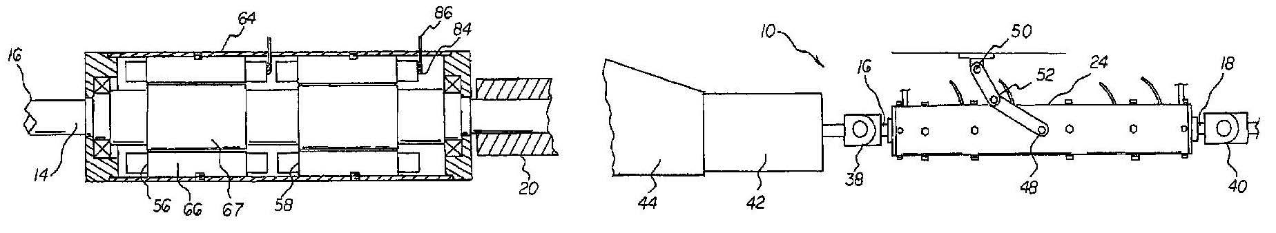
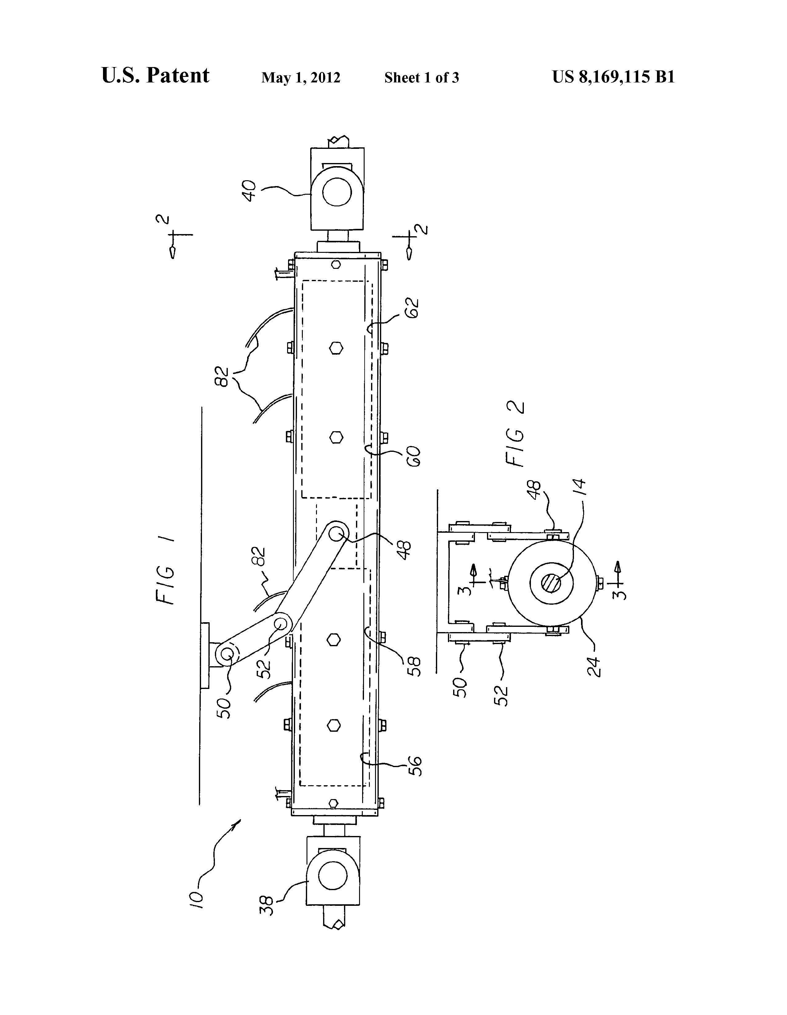
FIG. 1 is a side elevational view of a motor distributor
|
||
|
be utilized as a basis for the designing of other structures,
|
system constructed in accordance with the principles of the
|
||
|
methods and systems for carrying out the several purposes of
|
present invention.
|
||
|
the present invention. It is important, therefore, that the
|
FIG. 2 is a cross sectional view taken along line 2-2 of FIG.
|
||
|
claims be regarded as including such equivalent constructions
|
35
|
1.
|
|
|
insofar as they do not depart from the spirit and scope of the
|
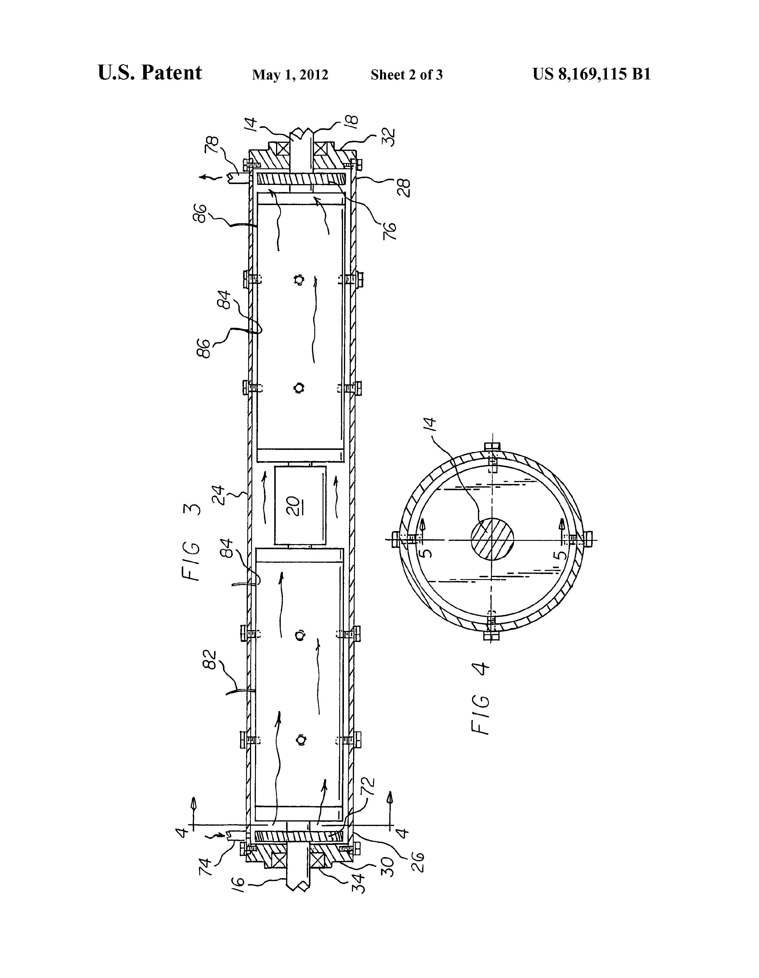
FIG. 3 is a cross sectional view taken along line 3-3 of FIG.
|
||
|
present invention.
|
2.
|
||
|
It is therefore an object of the present invention to provide
|
FIG. 4 is a cross sectional view taken along line 4-4 of FIG.
|
||
|
a new and improved motor distributor system which has all of
|
3.
|
||
|
the advantages of the prior art motor distributor systems of
|
40
|
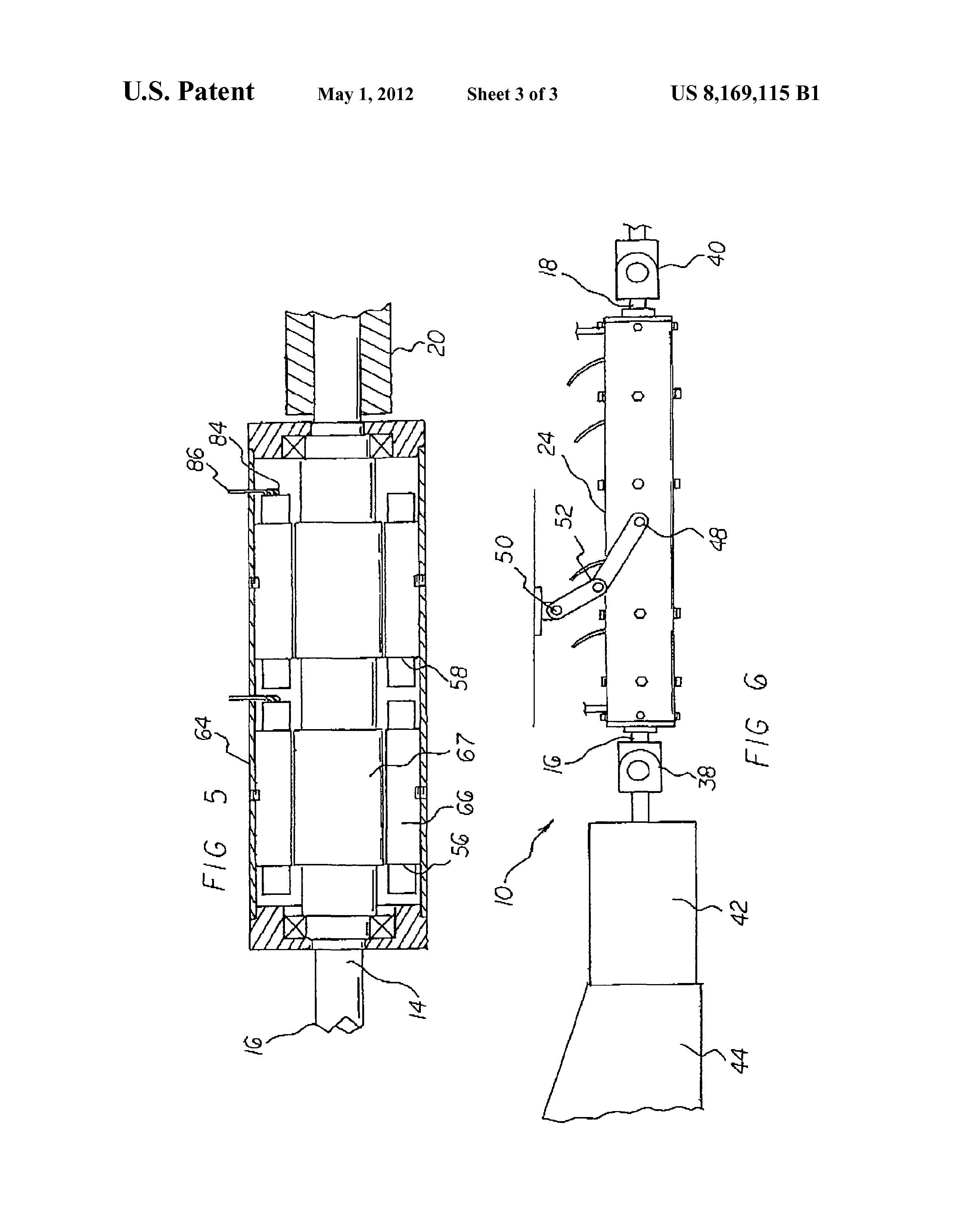
FIG. 5 is a cross sectional view taken along line 5-5 of FIG.
|
|
|
known designs and configurations and none of the disadvan
|
4.
|
||
|
tages.
|
FIG. 6 is a side elevational view similar to FIG. 1 but
|
||
|
It is another object of the present invention to provide a new
|
showing additional components.
|
||
|
and improved motor distributor system which may be easily
|
The same reference numerals refer to the same parts
|
||
|
and efficiently manufactured and marketed.
|
45
|
throughout the various Figures.
|
|
|
It is further object of the present invention to provide a new
|
|||
|
and improved motor distributor system which is of durable
|
DESCRIPTION OF THE PREFERRED
|
||
|
and reliable constructions.
|
EMBODIMENT
|
||
|
An even further object of the present invention is to provide
|
|||
|
a new and improved motor distributor system which is sus-
|
50
|
With reference now to the drawings, and in particular to
|
|
|
ceptible of a low cost of manufacture with regard to both
|
FIG. 1 thereof, the preferred embodiment of the new and
|
||
|
materials and labor, and which accordingly is then suscep
|
improved motor distributor system embodying the principles
|
||
|
tible of low prices of sale to the consuming public, thereby
|
and concepts of the present invention and generally desig
|
||
|
making such motor distributor system economically available
|
nated by the reference numeral10 will be described.
|
||
|
to the buying public.
|
55
|
The present invention, the motor distributor system 10 is
|
|
|
Even still another object of the present invention is to
|
comprised of a plurality of components. Such components in
|
||
|
provide a motor distributor system for powering a vehicle by
|
their broadest context include cylindrical drive shaft, a fixed
|
||
|
transmitting rotational energy through a drive shaft from an
|
cylindrical housing, an axial flux permanent magnet motor,
|
||
|
internal combustion engine and/or one or more axial flux
|
and electrical lines. Such components are individually con
|
||
|
permanent magnet motors, the powering being achieved in an
|
60
|
figured and correlated with respect to each other so as to attain
|
|
|
energy efficient manner which is safe, ecological, efficient
|
the desired objective.
|
||
|
and economical.
|
First provided is a cylindrical drive shaft 14. The drive shaft
|
||
|
Lastly, it is an object of the present invention to provide a
|
has a central axis. The drive shaft is rotatable around its
|
||
|
new and improved motor distributor system. A cylindrical
|
central axis. The drive shaft has a forward end 16. The drive
|
||
|
drive shaft has forward and rearward ends. A fixed cylindrical
|
65
|
shaft has a rearward end 18. A center is provided between the
|
|
|
housing receives the drive shaft, the housing having forward
|
forward and rearward ends. The drive shaft is discontinuous
|
||
|
and rearward ends. An axial flux permanent magnet motor
|
at its center. In this manner a forward portion and a rearward
|
US 8,169,115 B1
|
5
|
6
|
||
|
portion are formed. A connector 20 is provided. The connec
|
motors have windings and some are made of composite mate
|
||
|
tor joins the forward and rearward portions.
|
rial whereas the magnets are placed into the composite using
|
||
|
A fixed cylindrical housing 24 is provided. The housing has
|
windings only on one side. As such, means other than wind
|
||
|
a forward end 26. The housing has a rearward end 28. The
|
ings are adapted to be utilized for conducting electricity to the
|
||
|
housing has a central axis. The central axis is coextensive with
|
5
|
magnets.
|
|
|
the central axis of the drive shaft. The forward end of the drive
|
Further provided is a forward fan 72. The forward fan is
|
||
|
shaft extends forwardly of the forward end of the housing.
|
provided within the housing adjacent to the forward end cap.
|
||
|
The rearward end of the drive shaft extends rearwardly of the
|
An air inlet 74 is provided. The air inlet is provided within the
|
||
|
rearward end of the housing. The housing has a forward end
|
housing adjacent to the forward fan. A rearward fan 76 is
|
||
|
cap 30. The forward end cap is removably coupled to the
|
10
|
provided. The rearward fan is provided within the housing
|
|
|
forward end of the housing. The housing has a rearward end
|
adjacent to the rearward end cap. An air outlet 78 is provided.
|
||
|
cap 32. The rearward end cap is removably coupled to the
|
The air outlet is provided in the housing adjacent to the
|
||
|
forward end of the housing. Each end cap has a central aper
|
rearward fan.
|
||
|
ture. A bearing 34 is provided. The bearing rotatably supports
|
Provided last are electrical lines 82. The electrical lines
|
||
|
the drive shaft. The housing is fabricated of a rigid material.
|
15
|
have lower ends 84. The lower ends are coupled to the wind
|
|
|
The rigid material is chosen from the class of rigid materials.
|
ings in the exterior cylinders. The electrical lines have upper
|
||
|
The class of rigid materials includes an aircraft grade alumi
|
ends 86. The upper ends are adapted to be coupled to a source
|
||
|
num, other metals and composite materials.
|
of electrical potential. The electrical potential is adapted to
|
||
|
Provided next is a forward universal coupling 38. The
|
energize the axial flux permanent magnet motors. In this
|
||
|
forward universal coupling is secured to the forward end of
|
20
|
manner the load on the internal combustion engine is relieved
|
|
|
the drive shaft. A rearward universal coupling 40 is provided.
|
for increased efficiency of the system.
|
||
|
The rearward universal coupling is secured to the rearward
|
Note is taken that the axial flux permanent magnet motors
|
||
|
end of the drive shaft. The rearward universal coupling is
|
are adapted to be single phase or 3 phase. Further, the axial
|
||
|
adapted to couple to a rear axle and driven wheels. A clutch 42
|
flux permanent magnet motors are adapted to be AC or DC.
|
||
|
is optionally provided. The clutch is provided forwardly of
|
25
|
As to the manner of usage and operation of the present
|
|
|
the forward universal coupling. An internal combustion
|
invention, the same should be apparent from the above
|
||
|
engine 44 is provided. The internal combustion engine is
|
description. Accordingly, no further discussion relating to the
|
||
|
provided forwardly of the clutch. In this manner activation of
|
manner of usage and operation will be provided.
|
||
|
the internal combustion engine is adapted to rotate the drive
|
With respect to the above description then, it is to be
|
||
|
shaft. Further in this manner the rear axle and driven wheels
|
30
|
realized that the optimum dimensional relationships for the
|
|
|
are powered.
|
parts of the invention, to include variations in size, materials,
|
||
|
A support linkage is provided. The support linkage has
|
shape, form, function and manner of operation, assembly and
|
||
|
lower ends 48. The lower ends are coupled to the housing at a
|
use, are deemed readily apparent and obvious to one skilled in
|
||
|
central region. The support linkage has upper ends 50. The
|
the art, and all equivalent relationships to those illustrated in
|
||
|
upper ends are adapted to be coupled to a frame portion of the
|
35
|
the drawings and described in the specification are intended to
|
|
|
vehicle. The support linkage has resilient joints 52. The resil
|
be encompassed by the present invention.
|
||
|
ient joints are provided between the upper and lower ends. In
|
Therefore, the foregoing is considered as illustrative only
|
||
|
this manner the housing is allowed to absorb shocks and
|
of the principles of the invention. Further, since numerous
|
||
|
vibration during use.
|
modifications and changes will readily occur to those skilled
|
||
|
A single housing and support linkage is illustrated as the
|
40
|
in the art, it is not desired to limit the invention to the exact
|
|
|
preferred embodiment. It should be understood, however, that
|
construction and operation shown and described, and accord
|
||
|
any number of housings with their contained axial flux per
|
ingly, all suitable modifications and equivalents may be
|
||
|
manent magnet motors is adapted to be utilized in a single
|
resorted to, falling within the scope of the invention.
|
||
|
vehicle with their placement being as needed for the particu
|
What is claimed as being new and desired to be protected
|
||
|
lar application.
|
45
|
by Letters Patent of the United States is as follows:
|
|
|
A forward and a rearward axial flux permanent magnet
|
1. A motor distributor system for powering a vehicle by
|
||
|
motor 56, 58, 60, 62 are provided next. Such motors are
|
transmitting rotational energy through a drive shaft, in a first
|
||
|
brushless in the preferred embodiment, but the motors, in an
|
mode, from an internal combustion engine and, in a second
|
||
|
alternate embodiment of the invention, are adapted to be of
|
mode, from axial flux permanent magnet motors and, in a
|
||
|
the type to utilize brushes. The motors encompass the forward
|
50
|
third mode, from the combination of an internal combustion
|
|
|
and rearward portions of the drive shaft within the housing.
|
engine and axial flux permanent magnet motors, the powering
|
||
|
Each axial flux permanent magnet motor has a radially exte
|
being achieved in an energy conserving manner that is safe,
|
||
|
rior cylinder 64. The radially exterior cylinder is fixedly
|
ecological, efficient and economical, the system comprising,
|
||
|
secured to the housing. Each axial flux permanent magnet
|
in combination:
|
||
|
motor has a radially interior cylinder 66. The radially interior
|
55
|
a cylindrical drive shaft having a central axis, the drive
|
|
|
cylinder is secured to the drive shaft for rotation therewith.
|
shaft having a central axis and being rotatable around the
|
||
|
Each axial flux permanent magnet motor has windings. The
|
central axis, the drive shaft having a forward end and a
|
||
|
windings are coupled to the exterior cylinder. Each axial flux
|
rearward end with a center there between, the drive shaft
|
||
|
permanent magnet motor has a permanent magnet. The per
|
being discontinuous at the center thus forming a forward
|
||
|
manent magnet is fixedly coupled to the interior cylinder. The
|
60
|
portion and a rearward portion with a connector joining
|
|
|
interior and exterior cylinders are fabricated of a rigid, elec
|
the forward and rearward portions;
|
||
|
trically insulating material. The rigid, electrically insulating
|
a fixed cylindrical housing having a forward end and a
|
||
|
material is chosen from the class of electrically insulating
|
rearward end, the housing having a central axis coexten
|
||
|
materials. The class of electrically insulating materials
|
sive with the central axis of the drive shaft, the forward
|
||
|
includes composite materials and plastic materials.
|
65
|
end of the drive shaft extending forwardly of the forward
|
|
|
With regard to an alternate embodiment of the invention, it
|
end of the housing, the rearward end of the drive shaft
|
||
|
should be understood that some axial flux permanent magnet
|
extending rearwardly of the rearward end of the housing,
|
US 8,169,115 B1
|
7
|
8
|
||
|
a forward end cap removably coupled to the forward end
|
2. A motor distributor system comprising:
|
||
|
of the housing, a rearward end cap removably coupled to
|
a cylindrical drive shaft having forward and rearward ends;
|
||
|
the forward end of the housing, a central aperture in each
|
a fixed cylindrical housing receiving the drive shaft, the
|
||
|
end cap with a bearing rotatably supporting the drive
|
housing having forward and rearward ends;
|
||
|
shaft, the housing being fabricated of a rigid material
|
5
|
a plurality of axial flux permanent magnet motors encom
|
|
|
chosen from the class of rigid materials including an
|
passing the drive shaft within the housing, each axial
|
||
|
aircraft grade aluminum, other metals and composite
|
flux permanent magnet motor having a radially exterior
|
||
|
materials;
|
cylinder fixedly secured to the housing and a radially
|
||
|
a forward universal coupling secured to the forward end of
|
interior cylinder secured to the drive shaft for rotation
|
||
|
the drive shaft, a rearward universal coupling secured to
|
10
|
therewith, each axial flux permanent magnet motor hav
|
|
|
the rearward end of the drive shaft, the rearward univer-
|
ing windings coupled to the exterior cylinder, each axial
|
||
|
sal coupled to a rear axle and driven wheels, an optional
|
flux permanent magnet motor having a permanent mag
|
||
|
clutch forwardly of the forward universal coupling with
|
net fixedly coupled to the interior cylinder;
|
||
|
an internal combustion engine forwardly of the clutch
|
electrical lines having lower ends coupled to the windings
|
||
|
activation of internal combustion engine rotatably
|
15
|
and upper ends coupled to a source of potential for
|
|
|
coupling the drive shaft to power the rear axle and driven
|
energizing the axial flux permanent magnet motor; and
|
||
|
wheels;
|
a forward universal coupling secured to the forward end of
|
||
|
a support linkage having lower ends coupled to the housing
|
the drive shaft, a rearward universal coupling secured to
|
||
|
at a central region, the support linkage having upper ends
|
the rearward end of the drive shaft, the rearward univer
|
||
|
coupled to a frame portion of the vehicle, the support
|
20
|
sal coupling to a rear axle and driven wheels, a clutch
|
|
|
linkage having resilient joints between the upper and
|
forwardly of the forward universal coupling with an
|
||
|
lower ends for allowing the housing to absorb shocks
|
internal combustion engine forwardly of the clutch, acti
|
||
|
and vibration during use;
|
vation of the internal combustion engine coupling to
|
||
|
a forward and a rearward axial flux permanent magnet
|
rotate the drive shaft to power the rear axle and driven
|
||
|
motor encompassing the forward and rearward portions
|
25
|
wheels.
|
|
|
of the drive shaft within the housing, each axial flux
|
3. A motor distributor system comprising:
|
||
|
permanent magnet motor having a radially exterior cyl
|
a cylindrical drive shaft having forward and rearward ends·
|
||
|
inder fixedly secured to the housing and a radially inte
|
a fixed cylindrical housing receiving the drive shaft, the
|
||
|
rior cylinder secured to the drive shaft for rotation there
|
housing having forward and rearward ends;
|
||
|
with, each axial flux permanent magnet motor having
|
30
|
a plurality of axial flux permanent magnet motors encom
|
|
|
windings coupled to the exterior cylinder, each axial flux
|
passing the drive shaft within the housing, each axial
|
||
|
permanent magnet motor having a permanent magnet
|
flux permanent magnet motor having a radially exterior
|
||
|
fixedly coupled to the interior cylinder, the interior and
|
cylinder fixedly secured to the housing and a radially
|
||
|
exterior cylinder's being fabricated of a rigid, electrically
|
interior cylinder secured to the drive shaft for rotation
|
||
|
insulating material chosen from the class of electrically
|
35
|
therewith, each axial flux permanent magnet motor hav
|
|
|
insulating materials including composite materials and
|
ing windings coupled to the exterior cylinder, each axial
|
||
|
plastic materials;
|
flux permanent magnet motor having a permanent mag
|
||
|
a forward fan within the housing adjacent to the forward
|
net fixedly coupled to the interior cylinder;
|
||
|
end cap with an air inlet in the housing adjacent to the
|
electrical lines having lower ends coupled to the windings
|
||
|
forward fan, a rearward fan within the housing adjacent
|
40
|
and upper ends coupled to a source of potential for
|
|
|
to the rearward end cap with an air outlet in the housing
|
energizing the axial flux permanent magnet motor;
|
||
|
adjacent to the rearward fan; and
|
a support linkage having lower ends coupled to the housing
|
||
|
electrical lines having lower ends coupled to the windings
|
at a central region, the support linkage having upper ends
|
||
|
in the exterior cylinders and upper ends coupled to a
|
coupled to a frame portion of the vehicle, the support
|
||
|
source of electrical potential, the electrical potential
|
45
|
linkage having resilient joints between the upper and
|
|
|
energizing the axial flux permanent magnet motors to
|
lower ends for allowing the housing to absorb shocks
|
||
|
relieve the load on the internal combustion engine for
|
and vibration during use.
|
||
|
increased efficiency of the system.
|
* * * * *
|