Attached files
| file | filename |
|---|---|
| 8-K - 8-K - OGLETHORPE POWER CORP | a2202890z8-k.htm |
Exhibit 99.1
|
|
Oglethorpe Power Corporation March 21, 2011 Fourth Quarter and Year End 2010 Investor Briefing |

|
|
2 Participants Tom Smith President and Chief Executive Officer Betsy Higgins Executive Vice President and Chief Financial Officer Mike Price Executive Vice President and Chief Operating Officer |

|
|
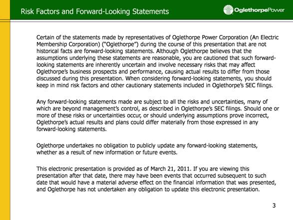
3 Certain of the statements made by representatives of Oglethorpe Power Corporation (An Electric Membership Corporation) (“Oglethorpe”) during the course of this presentation that are not historical facts are forward-looking statements. Although Oglethorpe believes that the assumptions underlying these statements are reasonable, you are cautioned that such forward-looking statements are inherently uncertain and involve necessary risks that may affect Oglethorpe’s business prospects and performance, causing actual results to differ from those discussed during this presentation. When considering forward-looking statements, you should keep in mind risk factors and other cautionary statements included in Oglethorpe’s SEC filings. Any forward-looking statements made are subject to all the risks and uncertainties, many of which are beyond management’s control, as described in Oglethorpe’s SEC filings. Should one or more of these risks or uncertainties occur, or should underlying assumptions prove incorrect, Oglethorpe’s actual results and plans could differ materially from those expressed in any forward-looking statements. Oglethorpe undertakes no obligation to publicly update any forward-looking statements, whether as a result of new information or future events. This electronic presentation is provided as of March 21, 2011. If you are viewing this presentation after that date, there may have been events that occurred subsequent to such date that would have a material adverse effect on the financial information that was presented, and Oglethorpe has not undertaken any obligation to update this electronic presentation. Risk Factors and Forward-Looking Statements |
|
|
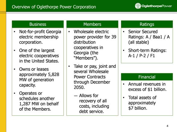
Overview of Oglethorpe Power Corporation Business Members Ratings Not-for-profit Georgia electric membership corporation. One of the largest electric cooperatives in the United States. Owns or leases approximately 5,828 MW of generation capacity. Operates or schedules another 1,287 MW on behalf of the Members. Wholesale electric power provider for 39 distribution cooperatives in Georgia (the “Members”). Take or pay, joint and several Wholesale Power Contracts through December 2050. Allows for recovery of all costs, including debt service. Senior Secured Ratings: A / Baa1 / A (all stable) Short-term Ratings: A-1 / P-2 / F1 Financial Annual revenues in excess of $1 billion. Total assets of approximately $7 billion. |
|
|
Member Systems and Service Territory Members’ service territory: Serves 1.8 million meters, representing approximately 4.1 million people. Covers 38,000 square miles, or 65 percent of Georgia. Includes 151 out of 159 counties in Georgia. Members’ load: Approximately 2/3 residential. Exclusive right to provide retail service in designated service territories. No residential competition. Competition only at inception for C&I loads in excess of 900kW. In 2010, Cobb EMC, Jackson EMC and Sawnee EMC accounted for 14.5%, 11.6%, and 10.6% of Oglethorpe’s total revenues, respectively. No other Member over 10%. The top 15 Members accounted for approximately 80% of total revenue in 2010. = Oglethorpe’s Members 2010 Member Customer Base by MWh Sales |
|
|
Residential Retail Rate Comparison (Cents per kWh) Members’ Competitive Position (a) Source: Georgia Power Company 2009 Form 10-K U.S. Residential Retail Average (2010) = 11.93 cents per kWh (a) 10.3 8.2 8.2 8.8 9.1 9.3 9.8 10.2 9.1 8.9 8.6 7.6 7.3 10.0 6 7 8 9 10 11 2003 2004 2005 2006 2007 2008 2009 Oglethorpe Member Average Georgia Power |
|
|
Diverse Mix of Generating Resources (a) Represents resources owned, leased, or operated by Oglethorpe. Excludes Members’ SEPA allocation. Capacity reflects planning capacity. Energy from pumped storage hydro is included above as well as energy from Member owned Smarr EMC assets (Smarr and Sewell Creek Energy Facilities) neither of which is included in Sales to Members represented in Oglethorpe’s most recent Form 10-K. ~6,500 MW ~24.3 Million MWh 2010 Capacity(a) 2010 Energy(a) 11% 41% 44% 4% 46% 19% 23% 12% Rocky Mountain Pumped Storage Hydro Sewell Creek Energy Facility Chattahoochee Energy Facility Hawk Road Energy Facility Plant Wansley Talbot Energy Facility Hartwell Energy Facility Plant Vogtle Plant Hatch Doyle Generating Plant Smarr Energy Facilitiy Plant Scherer Murray I & II (Pending Acquisition) |
|
|
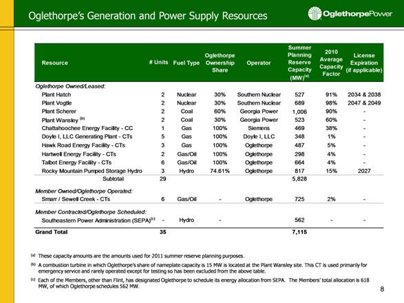
Oglethorpe’s Generation and Power Supply Resources (a) These capacity amounts are the amounts used for 2011 summer reserve planning purposes. (b) A combustion turbine in which Oglethorpe’s share of nameplate capacity is 15 MW is located at the Plant Wansley site. This CT is used primarily for emergency service and rarely operated except for testing so has been excluded from the above table. (c) Each of the Members, other than Flint, has designated Oglethorpe to schedule its energy allocation from SEPA. The Members’ total allocation is 618 MW, of which Oglethorpe schedules 562 MW. Resource Fuel Type Oglethorpe Ownership Share Operator Summer Planning Reserve Capacity (MW)(a) 2010 Average Capacity Factor License Expiration (if applicable) Oglethorpe Owned/Leased: Plant Hatch 2 Nuclear 30% Southern Nuclear 527 91% 2034 & 2038 Plant Vogtle 2 Nuclear 30% Southern Nuclear 689 98% 2047 & 2049 Plant Scherer 2 Coal 60% Georgia Power 1,006 90% - Plant Wansley (b) 2 Coal 30% Georgia Power 523 60% - Chattahoochee Energy Facility - CC 1 Gas 100% Siemens 469 38% - Doyle I, LLC Generating Plant - CTs 5 Gas 100% Doyle I, LLC 348 1% - Hawk Road Energy Facility - CTs 3 Gas 100% Oglethorpe 487 5% - Hartwell Energy Facility - CTs 2 Gas/Oil 100% Oglethorpe 298 4% - Talbot Energy Facility - CTs 6 Gas/Oil 100% Oglethorpe 664 4% - Rocky Mountain Pumped Storage Hydro 3 Hydro 74.61% Oglethorpe 817 15% 2027 Subtotal 29 5,828 Member Owned/Oglethorpe Operated: Smarr / Sewell Creek - CTs 6 Gas/Oil - Oglethorpe 725 2% - Member Contracted/Oglethorpe Scheduled: Southeastern Power Administration (SEPA)(c) - Hydro - 562 - - Grand Total 35 7,115 # Units |
|
|
Planned Acquisition: Murray I & II Combined Cycle Facilities On January 31, 2011, OPC entered into a Purchase and Sale Agreement with KGen Power Corporation to acquire two combined cycle facilities. The Murray I and Murray II natural gas units are located outside of Dalton, Georgia. Have a combined summer planning reserve generating capacity of ~1,220 MW. Purchase price, exclusive of working capital and other closing adjustments, is approximately $531 million. Oglethorpe has completed its due diligence and its Board and Member Systems, as well as KGen’s Board and shareholders, have approved the transaction. Closing anticipated in April 2011 subject to applicable regulatory approvals and other customary closing conditions. Most Members are not expected to need the power until 2015/2016; as such, Oglethorpe will market power out of the facilities until then. Oglethorpe will defer the net carrying costs during this period and recover such costs after the facilities are made available to the Members. Have submitted loan application for permanent financing from RUS. Anticipate approximately 2 year period for loan approval and funding from RUS. If RUS financing is ultimately not available, anticipate using taxable bonds for permanent financing. Interim financing will be provided by a $260 MM 3-Year Bank Term Loan and the remainder will be funded with a combination of cash and draws on existing credit facilities. |
|
|
Reduction in Planned CapEx With the Murray acquisition, Oglethorpe would cancel its $750 million self-build combined cycle plant. $4.2 million spent through year end 2010 (excluding land and NOx offsets). Vogtle 3 & 4 participation not affected by this acquisition. Independently of this acquisition, Oglethorpe has deferred the $477 million Warren Biomass Project (but will continue to monitor regulatory and legislative developments related to the project) $11.6 million spent through year end 2010 (excluding land). Together, the acquisition of Murray and deferral of the biomass project would allow Oglethorpe to reduce previously projected construction related capital expenditures by $1.2 billion through 2015 (exclusive of the acquisition price). Murray I |
|
|
New Westinghouse AP1000 units will be adjacent to existing two units at Vogtle site. Experienced developer and operator, Southern Nuclear. Very favorable EPC contract with experienced contractors, Westinghouse and Stone & Webster consortium, which includes parent guarantees. In 2010, amended to replace certain index-based adjustments with fixed escalation amounts. 30% share (660 MW) of 2,200 MW total capacity from additional units. Georgia Power, MEAG and City of Dalton are other co-owners. $4.2 billion estimated total cost to Oglethorpe (including AFUDC). Oglethorpe’s share is fully subscribed by its members. Vogtle Units 3 & 4 Project Highlights 2017 Unit 4 in Service 2005 2011 2010 2009 2007-2008 2006 May 2005 Development Agreement 2017 Mar 2008 File Combined Construction Operating License (COL) with NRC Aug 2009 NRC Issuance of ESP/LWA Q4 2011 NRC Issuance of COL (projected) 2016 Unit 3 in Service Feb 2010 DOE Offered Conditional Term Sheet Q2 2012 Potential Start of DOE Funding April 2006 Definitive Agreements Aug 2006 Early Site Permit (ESP) Filed with NRC May 2010 Signed DOE Conditional Term Sheet Time Now Q3 2011 DCD Final Rulemaking |
|
|
Design Control Document (DCD) Important target milestones achieved on schedule: December 21, 2010 - Advisory Committee on Reactor Safeguards (ACRS) issued letter to the NRC concluding AP1000 design is safe. Proposed DCD rulemaking posted in Federal Register February 24. Targeting September 2011 for DCD final rulemaking. Combined Construction & Operating License (COL) Several meetings of ACRS held in January to review portions of COL. ACRS issued letter to NRC on January 24 endorsing the COL application. Clears path for development of final safety reports and NRC hearings. Recent Events in Japan Key Vogtle Licensing Activities |
|
|
13 Financial Highlights Betsy Higgins Executive Vice President and Chief Financial Officer |

|
|
Member Demand Requirements Member Energy Requirements (MW) Percent Change (Million MWh) Percent Change 6.1% 10.4% 0.8% 10.4% 4.1% 3.9% 2.8% -0.3% -3.7% -5.3% Note: The data is at the Members’ delivery points (net of system losses). While Flint EMC was not a Member from 2005 through 2009, Flint EMC data is included in all years. However, Flint is not expected to purchase energy from Oglethorpe until 2016. Highest Summer Peak (2007) = 9294 MW Highest Winter Peak (2010) = 8462 MW 2010 Summer Peak = 8988 MW -2.0% Historical Load 9.1% 50 39 38 84 24 4 4 19 9 Days >= 90° Days >= 95° Days >= 100° 0 1,000 2,000 3,000 4,000 5,000 6,000 7,000 8,000 9,000 10,000 2005 2006 2007 2008 2009 2010 0.0 5.0 10.0 15.0 20.0 25.0 30.0 35.0 40.0 2005 2006 2007 2008 2009 2010 |
|
|
15 02,000 4,000 6,000 8,000 10,000 12,000 14,000 16,000 2011 2012 2013 2014 2015 2016 2017 2018 2019 2020 MW Total Existing CapacityMembers' Contract Resources: Hawk RoadMembers' Contract ResourcesNew Resource: Vogtle ExpansionNew Resource: Hawk RoadNew Resource: Murray AcquisitionRemaining NeedLoad plus Reserves(a) Represents resources owned, leased, contracted for, operated or scheduled by Oglethorpe (including SEPA). (b) Members’ contract capacity is estimated based on Oglethorpe’s knowledge of Member contracts, however Members are not generally obligated to disclose details of contractual arrangements to Oglethorpe, and therefore Members’ actual contract capacity may differ from that which is shown above. (c) Members’ remaining need may be met by a variety of options currently under consideration by the Members including extensions or replacements of existing contracts, additional combustion turbine facilities constructed by Oglethorpe or additional resources that Members may own directly. Members’ Forecasted Requirements and Identified Sources Includes “Subscribed” Oglethorpe Resources (a) (b) (c) |

|
|
16 Includes allowance for funds used during construction. Does not include any expenditures related to 605MW combined cycle or biomass plants. Capital Expenditures In addition to the amounts reflected as Future Generation above, we expect additional capital expenditures in the years 2014-2017 of approximately $1.3 billion to complete construction of Plant Vogtle Units No. 3 and No. 4. |
|
|
Submitted Part I and Part II loan applications in 2008. Signed conditional term sheet with DOE in May 2010. Final decision on loan approval is not expected to occur until after approval of the COLs (Combined Construction Permits Operating Licenses), currently anticipated in fourth quarter 2011. DOE loan guarantee targets 70% of eligible project costs, not to exceed $3.057 billion. All-in pricing expected to be favorable relative to taxable capital markets. Will be secured under Oglethorpe’s First Mortgage Indenture on parity with other secured debt. DOE Loan Guarantees for Vogtle 3 & 4 |
|
|
Vogtle Units 3 & 4 Financing Plan Vogtle 3 & 4 CWIP through 12/31/2010 total $867 Million DOE financing available only after receipt of COL (assumed in late 2011). OPC using commercial paper program and committed lines of credit for interim financing between permanent debt issuances shown below. |
|
|
RUS Loan Status (b) (a) Project has been deferred. RUS is currently completing NEPA process which would enable site development in the future, if desired. (b) When acquisition of Murray I & II is completed, this loan application will be withdrawn. (a) Approved Loans General Improvements 92,000,000.00 $ 42,240,000.00 $ 49,760,000.00 $General & Environmental Improvements 441,522,000.00 $ 235,067,000.00 $ 206,455,000.00 $ General & Environmental Improvements 310,228,000.00 $ 32,722,000.00 $ 277,506,000.00 $ Heard County/Hawk Road Acquisition 203,100,000.00 $ - $ 203,100,000.00 $ Hartwell Acquisition 170,000,000.00 $ - $ 170,000,000.00 $ 1,216,850,000 $ 310,029,000 $ 906,821,000 $ Submitted Loans Warren Biomass Facility 459,000,000 $ General Improvements 128,000,000 $ Subscribed CC Project 750,000,000 $ Murray Units I&II 535,000,000 $ Purpose/Use of Proceeds Amount Advanced (to date) Remaining Amount |
|
|
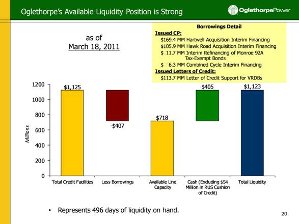
Oglethorpe’s Available Liquidity Position is Strong Borrowings Detail Issued CP: $169.4 MM Hartwell Acquisition Interim Financing $105.9 MM Hawk Road Acquisition Interim Financing $011.7 MM Interim Refinancing of Monroe 92A Tax-Exempt Bonds $6.3 MM Combined Cycle Interim Financing Issued Letters of Credit: $113.7 MM Letter of Credit Support for VRDBs as of March 18, 2011 Represents 496 days of liquidity on hand. $1,125 - $407 $718 $405 $1,123 0 200 400 600 800 1000 1200 Total Credit Facilities Less Borrowings Available Line Capacity Cash (Excluding $54 Million in RUS Cushion of Credit) Total Liquidity Millions |
|
|
$50M CoBank (Unsecured) $50M CFC (Unsecured) $475M Syndicated CP Backup (Unsecured) $250M CFC (Secured) $150M CoBank (Secured) Plus Optional Term-Out until 2043 $150M J.P. Morgan (Unsecured) Term of Existing Liquidity Facilities $475M Credit Facility - Participant Banks Commitment (Millions) Bank of America, N.A. - Administrative Agent $75 SunTrust Bank $75 The Bank of Tokyo - Mitsubishi UFJ, Ltd. $60 CoBank, ACB $60 J.P. Morgan Chase Bank, National Association $60 National Rural Utilities Cooperative Finance Corp $60 Wells Fargo Bank, N.A. $60 Goldman Sachs Bank $25 $1,200 $1,000 $800 $600 $400 $200 $0 Q1 2011 Q2 2011 Q3 2011 Q4 2011 Q1 2012 Q2 2012 Q3 2012 Q4 2012 Q1 2013 Q2 2012 Q3 2012 Q4 2012 Q1 2014 2043 |
|
|
Liquidity Strategy Major liquidity requirements include: Vogtle construction (through 2017). Murray interim financing. Credit support for VRDBs. Working capital (increasing in light of expanded business size). Liquidity will be used for interim acquisition and construction financing until permanent financing is obtained (RUS, DOE, first mortgage or unsecured bonds, etc.). Implementing $260 million bridge loan for a portion of the $531 million Murray acquisition cost. Remaining $271 million will be financed with a combination of cash and draws under bank credit facilities. Targeting total liquidity (not including Murray term loan) of: In excess of $1 billion syndicated credit facility to backup CP and certain VRDBs (by July). ~$500-700 million in bilateral lines for VRDBs and working capital needs (by October). ~$425 million average cash target. |
|
|
Income Statement Excerpts Margins for Interest ratio is calculated on an annual basis and is determined by dividing Oglethorpe’s Margins for Interest by Interest Charges, both as defined in Oglethorpe’s First Mortgage Indenture. The Indenture obligates Oglethorpe to establish and collect rates that, subject to any necessary regulatory approvals, are reasonably expected to yield a Margins for Interest ratio equal to at least 1.10x for each fiscal year. In addition, the Indenture requires a showing of Oglethorpe’s having met this requirement for certain historical periods as a condition for issuing additional obligations under the Indenture. For 2009 and 2010, Oglethorpe increased its Margins for Interest ratio to 1.12x and 1.14x, respectively, above the minimum 1.10x ratio required by the Indenture. For 2011, the board again approved a Margins for Interest ratio of 1.14x. Oglethorpe’s Board of Directors will continue to evaluate margin coverage throughout the construction period and may chose to further increase, or decrease, the Margins for Interest ratio in the future. December 31, ($ in thousands) 2010 2009 2008 Statement of Revenues and Expenses: Operating Revenues: Sales to Members $1,292,514 $1,144,012 $1,237,649 Sales to Non-Members 1,478 1,249 1,111 Operating Expenses 1,054,743 921,139 1,041,681 Other Income 43,651 42,728 43,381 Net Interest Charges (249,167) (240,460) (221,201) Net Margin $33,733 $26,390 $19,259 Margins for Interest Ratio (a) 1.14x 1.12x 1.10x Year Ended |

|
|
Fixed costs: Members billed based on board-approved annual budget and budget revisions throughout the year, if necessary. Prior period adjustment mechanism covers any year-end shortfall. Energy costs: Actual costs are passed through. Monthly true-up of estimate vs. actual. Rate Structure Assures Recovery of All Costs + Margin Note: First Mortgage Indenture requires an MFI ratio of least 1.10x (a) Based on proposed budget adjustment, subject to Board approval. Oglethorpe’s Board previously approved a 2011 Budget with a $38.3 million margin. MFI coverage requirement of 1.10x under First Mortgage Indenture. Budget of 1.14x MFI for 2010 and 2011. Formulary rate under Wholesale Power Contract. Designed to recover all costs, plus margin, without any further regulatory approval. Annual budget and adjustments to rate to reflect budget changes are generally not subject to approval of RUS or any other regulatory authority. Changes to rate schedule are subject to RUS approval. (Budgeted) 1.10 1.10 1.10 1.10 1.10 1.10 1.10 1.10 1.10 1.12 1.14 1.14 $20.0 $18.4 $17.5 $16.9 $17.2 $17.7 $18.2 $19.1 $19.3 $26.4 $33.7 $38.8(a) 0 10 20 30 40 1.06 1.08 1.10 1.12 1.14 1.16 2000 2001 2002 2003 2004 2005 2006 2007 2008 2009 2010 2011 Net Margin (Mn) MFI Coverage Margin Coverage |
|
|
Balance Sheet Excerpts (a) The equity ratio is calculated, pursuant to Oglethorpe’s First Mortgage Indenture, by dividing patronage capital and membership fees by total capitalization plus long-term debt due within one year (Total Long-Term Debt and Equities in the table above). Oglethorpe has no financial covenant that requires it to maintain a minimum equity ratio; however, a covenant in the Indenture restricts distributions of equity (patronage capital) to its Members if its equity ratio is below 20%. Oglethorpe also has a covenant in a credit agreement that currently requires a minimum total patronage capital of $545 million. The equity ratio is less than that of many investor-owned utilities because Oglethorpe operates on a not-for-profit basis and has a significant amount of authority to set and change rates to ensure sufficient cost recovery to produce margins to meet financial coverage requirements. December 31, ($ in thousands) 2010 2009 2008 Balance Sheet Data: Assets: Total Electric Plant $5,015,560 $4,400,496 $3,639,395 Cash and Cash Equivalents $672,212 $579,069 $167,659 Total Assets $6,997,062 $6,370,234 $5,044,452 Capitalization: Patronage Capital and Membership Fees $595,952 $562,219 $535,829 Accumulated Other Comprehensive Loss ($469) ($1,253) ($1,348) Subtotal $595,483 $560,966 $534,481 Long-term Debt and Obligations under Capital Leases $4,836,415 $4,387,926 $3,514,923 Obligation under Rocky Mountain Transactions $123,573 $115,641 $108,219 Long-term Debt and Capital Leases due within one year $170,947 $119,241 $110,647 Total Long-Term Debt and Equities $5,726,418 $5,183,774 $4,268,270 Equity Ratio (a) 10.4% 10.8% 12.6% December 31, |
|
|
Liquidity Margins for Interest Revenue Summary Interim Financing Long Term Debt Balance Sheet Electric Plant Total Energy: ~23 Million MWh Average Cost of Funds: 0.33% ($ in millions) LT Debt Outstanding (12.31.2010): $4.796 billion Weighted Average Cost: 5.22% Equity ratio: 10.4% Days Liquidity on Hand 1.14 MFI Interim Refinancing for Monroe 92A Tax-Exempt Bonds, $12 As of March 18, 2011 2010 2010 2010 2010 Note: Includes Major Maintenance Sinking Fund and Debt Service Adder |
|
|
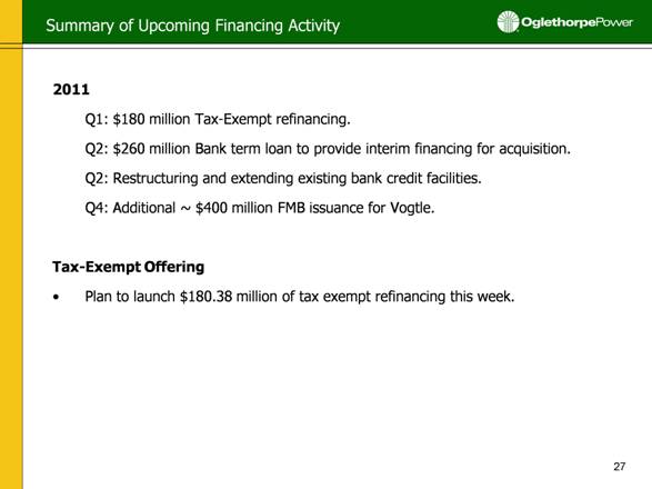
Summary of Upcoming Financing Activity 2011 Q1: $180 million Tax-Exempt refinancing. Q2: $260 million Bank term loan to provide interim financing for acquisition. Q2: Restructuring and extending existing bank credit facilities. Q4: Additional ~ $400 million FMB issuance for Vogtle. Tax-Exempt Offering Plan to launch $180.38 million of tax exempt refinancing this week. |
|
|
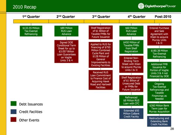
2010 Recap 1st Quarter 2nd Quarter 3rd Quarter 4th Quarter $133.55 Million Tax Exempt Refinancing Applied to RUS for financing of $750 Million Combined Cycle Plant and $128 Million of General Improvements to Existing Facilities Signed DOE Conditional Term Sheet for up to $3.057 Billion Loan Guarantees on Vogtle Units 3 & 4 Credit Facilities Debt Issuances Other Events Post-2010 Restructuring and Extending Bank Credit Facilities Additional FMB Issuance for Portion of Vogtle Units 3 & 4 not Financed by DOE Shelf Registration of $1 Billion of Unsecured Debt or FMBs for Future Issuance Ongoing Tax-Exempt Refinancings and Taxable Financings as Needed $89 Million RUS Loan Advance $60 Million RUS Loan Advance Entered Non-Binding Term Sheet with KGen to acquire Murray Units I & II Entered Purchase and Sale Agreement with KGen to acquire Murray Units I & II $450 Million of Taxable FMBs from Shelf Registration $180.38 Million Tax-Exempt Refinancing Refinanced $8 Million RUS Loan with CFC Shelf Registration of $1 Billion of Taxable FMBs for Future Issuance Extended $50 Million CoBank Credit Facility Received RUS Loan Commitment to Finance Cost of Acquiring Hawk Road and Hartwell Facilities $260 Million Bank Term Loan for Murray Acquisition |
|
|
Mike Price Executive Vice President and Chief Operating Officer Recent Events in Japan |

|
|
Recent Events in Japan Potential implications for existing nuclear units Potential implications for new Vogtle units under development Fact Sheets are included in Appendix. |
|
|
Oglethorpe is a Strong, Stable Credit One of the largest electric cooperatives in the United States. Oglethorpe has long-term, take-or-pay, joint and several Wholesale Power Contracts with its Members through 2050. Members' obligations under the Wholesale Power Contracts are joint and several. Primarily residential customer base — approximately 2/3 of Members’ MWh sales and operating revenue. Oglethorpe’s formulary rate structure assures cost recovery. Inputs to rate formula are not subject to any regulatory approval. Changes to formulary rate schedule are subject to RUS approval. Strong liquidity position. Well diversified power supply portfolio. Substantial value in existing resources. Strong, consistent operational and financial performance. Strong emphasis on risk management and corporate compliance. |
|
|
Additional Information A link to this presentation will be posted on Oglethorpe’s website www.opc.com. Oglethorpe’s SEC filings, including its annual reports on Form 10-K, quarterly reports on Form 10-Q, current reports on Form 8-K are made available on its website. For additional information please contact: Name Title Email Address Phone Number Betsy Higgins Executive Vice President and Chief Financial Officer betsy.higgins@opc.com 770-270-7168 Tom Brendiar Director, Bank and Investor Relations tom.brendiar@opc.com 770-270-7173 Joe Rick Director, Capital Markets joe.rick@opc.com 770-270-7240 |

|
|
Appendix |

Alvin W. Vogtle Nuclear Power Plant - Units 1&2
Pressurized Water Reactors (PWRs)
Plant Vogtle Fact Sheet
March 2011
· Plant Vogtle is designed to withstand an earthquake equal to the plant’s maximum projected seismic event.
· Plant Vogtle Units 1 & 2 are pressurized water reactors (PWRs)
· Plant Vogtle was designed in accordance with Nuclear Regulatory Commission (NRC) requirements related to natural events such as earthquakes, tornadoes, flooding (including tsunamis) and hurricanes. These requirements ensure that the plants can be safely shutdown and maintained in shutdown status after these events. The NRC requirements provide a design margin above historical event levels.
· Plant Vogtle, as well as federal, state, and local officials, has a detailed comprehensive emergency plan to respond to events within the plant’s design and beyond the plant’s design. Our trained skilled staff is on-site 24 hours per day and is trained to recognize and respond to problems. If an emergency occurs, the plant has the necessary equipment and plant personnel have detailed procedures and training to respond appropriately.
· Environmental hazards differ depending on location. For example, tsunamis or giant tidal waves are not credible events at Plant Vogtle because it is an inland site - located approximately 130 miles from the coast at an elevation of approximately 220 feet above sea level. Also, the Plant Vogtle site is located in an area of low seismic activity.
· Plant Vogtle is designed to withstand 0.20g horizontal peak ground acceleration which is well above any predicted earthquake ground motion in the area. This ground motion approximately represents an earthquake magnitude of 6.
· An independent seismic margins review, that was peer reviewed by seismic experts and submitted to the NRC, has confirmed Plant Vogtle is capable of sustaining an earthquake ground motion that is 50 percent higher than its design level and approximately represents an earthquake magnitude of 7.0.
· There are no active faults in the Plant Vogtle area and the site is in a low seismic zone. The site has had seismic instrumentation installed for over 20 years and has never recorded any earthquake ground motion. In the past 300 years, there has been no earthquake greater than a magnitude 3.7 in the surrounding area.
· Plant Vogtle is equipped with seismic monitoring systems that are set at extremely low triggering levels. If a seismic event triggers the seismic monitoring system, it would provide seismic ground motion data to the control room so the operators can determine the severity of the event and per procedures make appropriate decisions concerning plant safety.
· The building and structures that are necessary to maintain the plant in a safe condition are designed to withstand flooding and high winds. This includes flying debris produced by tornadoes with wind speeds up to 360 mph. The river water intake structure is designed to operate at very high river levels. Given the drainage capabilities of the Savannah River basin, it is highly unlikely a water source of this quantity would ever threaten the intake structure.
· All of Plant Vogtle’s safety-related structures and equipment are located at or above 220 feet mean sea level (MSL). A safety analysis evaluating the site’s vulnerability to floods, tsunamis, dam breaks and other events on
the Savannah River - including the failure of all upstream dams - determined that the maximum flood elevation that could result from such events is 168 MSL and would not impact Vogtle’s safety-related structures or equipment.
· Plant Vogtle has a wide array of plant systems that ensure redundancy and the capability to ensure the plant reaches cold shut down and maintains it.
Information from Plant Vogtle Media Guide
Complete Plant Vogtle Media Guide available online at:
http://www.southerncompany.com/nuclearenergy/SNCmedia/0700747-Vogtle%20Media%20Guide%20Insides.pdf
Plant Vogtle – Background Information
Plant Vogtle sits on a 3,200-acre site along the Savannah River, in Burke County near Waynesboro, Ga., and approximately 34 miles southeast of Augusta, Ga. Similar to other electric generating plants, Plant Vogtle has large turbines and generators, a computerized control room, and a chemistry lab, and is connected to the electric grid through high-voltage switchyards. However, massive containment buildings – with thick walls of concrete and steel house two 355-ton reactor vessels on huge concrete slabs. These concrete structures shield the environment from radiation. The 548-foot-high twin cooling towers can be seen for miles.
Plant Vogtle – Accident prevention details
One essential point about Plant Vogtle’s reactors is that they cannot explode like a nuclear weapon. Nuclear weapons are made of highly enriched uranium or virtually pure plutonium. No nuclear explosion is possible with the low-enriched fuel used to produce electricity.
The core of a reactor contains a large amount of highly radioactive material at high temperature and pressure. The chief danger is a loss of cooling water, causing a build-up of heat that would damage or melt the fuel rods.
To prevent this, commercial nuclear power plants are designed with a strategy of defense-in-depth. The first layer of designed features is essentially self-regulating. In general, the fission process slows as the coolant temperature rises.
Other passive systems include physical barriers that restrict the spread of contamination outside the primary systems. Barriers such as the fuel’s zirconium alloy cladding, the thick reactor vessel and the thick concrete containment provide protection in case of an accident.
Following is a description of these physical barriers at Plant Vogtle that keep radioactive fission products from reaching the environment.
Fuel cladding – Uranium fuel used at Plant Vogtle is in the form of a ceramic “pellet” which normally houses 99.99 percent of the radioactive fission products. These fuel pellets are stacked inside tubes. The tubes are arranged in fuel assemblies and are placed within the reactor vessel, comprising the core.
Reactor vessel – The reactor vessel is a barrel-like structure about 16 feet in diameter with carbon steel walls lined with stainless steel. It is located inside the lower part of the containment building. The reactor vessel with its attached
pipes, reactor coolant pumps and the pressurizers comprise the primary coolant system boundary. This keeps any fission products, which may escape the cladding in the event of broken fuel tubes, from reaching the rest of the plant.
Containment – The containment building is constructed to prevent the inadvertent release of radioactivity to the environment under both normal operating conditions and the most severe of accident conditions. Therefore, all systems that potentially could release large amounts of radioactivity are located in the containment structure. At Plant Vogtle, the containment structure houses the reactor vessel and the reactor cooling system with its steam generators, reactor coolant pumps and pressurizer. The containment building is made of concrete with thick walls. The concrete is post-tensioned and reinforced with a network of steel rods (rebar), each about the thickness of a human forearm. The structure is lined with thick steel and is designed to withstand extreme temperatures and pressures which might result from a serious accident. The containment is sealed and must be entered and exited through special air-lock chambers. Most penetrations such as pipes or conduits entering the containment walls have automatic valves that close at the first sign of trouble, isolating and sealing off the containment to prevent leakage.
As a Category 1 Seismic structure, the containment building can withstand powerful earthquakes and high winds. It can survive tornado winds of 360 miles per hour, as well as the impact of tornado missiles such as utility poles or even something as massive as an automobile. In addition, since 9-11, studies have been conducted to analyze a commercial aircraft crash into the reactor containment building and the impact on the containment building’s structural strength. A comprehensive study conducted by the Electric Power Research Institute concluded that the containment structures that house nuclear fuel are robust and would protect the fuel from impacts of large commercial aircraft.
Engineered Safety Systems - The function of the Engineered Safety Systems is to contain, control, mitigate, and terminate accidents and to maintain safe radiation exposure levels below applicable federal limits and guidelines. Some of the safety-related systems defined as Engineered Safety Systems for Plant Vogtle are:
Reactor protection system – The reactor protection system is designed to shut down the reactor safely. The system continuously monitors important plant parameters. If a problem occurs and causes the reactor power, pressures, temperatures, coolant flow rates or other plant parameters to exceed prescribed limits, the reactor shuts down automatically by the immediate insertion of all control rods into the core. The reactor also can be shut down manually if the reactor operator determines that a potentially unsafe condition exists.
Emergency Core Cooling Systems (ECCS) – The most immediate action to be taken after a Loss of Coolant Accident is to replenish cooling water back into the reactor and to assure that the core remains under water. The function of the ECCS is to provide the reactor with emergency cooling water after normal cooling water has been lost. There are two Emergency Core Cooling Systems, each designed to be completely redundant. Their operation is initiated either manually by an operator or automatically when the control systems in the plant detect an accident condition. Both the High Pressure Injection and Low Pressure Injection systems can inject water for long periods, pumping water supplied either from the refueling water storage tank or through recirculation from the containment sump.
Auxiliary feedwater system – The auxiliary feedwater system (AFW) serves a dual purpose. During normal plant startup or hot standby, it provides the secondary side of the steam generators with condensate. As mentioned before, the condensate picks up the heat from the primary coolant, boils and becomes the main steam for the turbine. This lowers the heat of the primary coolant, while providing steam for plant-related operations. During accident conditions, the AFW receives heat from the primary coolant. For example, if the plant were to lose all electric power, the AFW – using pumps driven by steam turbines (not requiring electricity) – could cool down the primary side and maintain the plant in a safe shutdown condition until power is restored.
Emergency power – During normal operations and when the plant is shut down, components that could be used in emergency situations are powered with electricity from the off-site power grid. Plant Vogtle Units 1 and 2 have two
emergency diesel generators each. Either of these generators is designed to supply the power needed for safe operation of the plant’s emergency systems if off-site power is not available. Additionally, most of the safety-related instrumentation needed for safe shutdown of the plant can be operated by DC batteries that are constantly kept charged and ready for service if all other power sources should fail. Finally, even without any electrical power available, the plant can be shut down safely and cooled by using the natural circulation of the primary system while manually venting steam from the secondary side of the steam generator. Water for the steam generator is provided using the steam-driven auxiliary feed pump.
Containment isolation system – The purpose of this system is to isolate and close all openings to the containment if a high radiation situation exists in the containment building. Automatic signals are sent to appropriate valves and dampers to close, thus isolating all containment penetrations – except for those needed for the operation of the Emergency Core Cooling Systems.
Habitability systems – The control room heating, ventilation and air conditioning (HVAC) system protects control room personnel from accident conditions. The atmosphere inside the control room can be isolated from the rest of the plant and the outside environment to keep out radiation, smoke, toxic substances and other harmful airborne contaminants.
Combustible gas control system – The combustible gas control system monitors the atmosphere inside containment.
In summary, Plant Vogtle has a number of redundant safety systems to prevent an emergency at the plant and to restore the plant to safe conditions.
Plant Vogtle – Facts & Statistics
Owners
Georgia Power Company 45.7%
Oglethorpe Power Company 30.0%
Municipal Electric Authority Of Georgia 27.7%
City of Dalton 1.6%
Operator
Southern Nuclear Operating Company
Location
Burke County, Ga., approximately 34 miles southeast of Augusta, on the Savannah River.
Nearest City
Waynesboro, Ga., 21 miles west
Reactors
Type - pressurized water reactors (PWRs). Two units
Turbine Generator: 1,225 megawatts per unit
Total Capacity – 2,450 megawatts
Nuclear Steam Supply System (Reactor Manufacturer)
Westinghouse Electric Company
Turbine Generator Manufacturer
General Electric Company
Containment
Vertical cylindrical, post-tensioned concrete structure with a dome and a flat base. It houses reactor, reactor coolant system and other Nuclear Steam Supply System (NSSS) components. The interior is lined with carbon steel plate. Concrete shields the reactor and other NSSS components. It is 140 feet in diameter and 226 feet high. Minimum vertical wall thickness is 3 feet 9 inches. Minimum dome thickness is 3 feet and 6 inches with a foundation thickness of 10 feet.
ARCHITECT/ENGINEER:
Bechtel Power Corporation and Southern Company Services, Inc.
COST:
$8.87 billion (including financing)
APPROXIMATE EMPLOYMENT:
900
CONSTRUCTION START DATE:
1974
OPERATING LICENSE
Unit 1 – March 16, 1987
Unit 2 – March 31, 1989
COMMERCIAL OPERATION:
Unit 1 – June 1987
Unit 2 – June 1989
LICENSE RENEWALS:
Granted June 3, 2009
Unit 1: January 16, 2047 (Originally licensed until 2027)
Unit 2: February 9, 2049 (Originally licensed until 2029)
SIZE OF SITE:
3,150 acres
Fuel (17x17 array)
Fuel assemblies: 193
Overall length of fuel assembly: approximately 14 feet
Fuel rods per assembly: 264
Control Rods
(Rod Cluster Control Assemblies – RCCAs)
Number of RCCAs: 53
Control rods per RCCA: 24
Absorber material composition: silver-indium-cadmium
Cladding: stainless steel
Emergency Power (Safety Related)
Diesel generators: 2 per unit
Rated capacity: 7 MW each
Four 125-volt DC buses per unit
Reactor Coolant System (RCS)
Four loops, each loop with a reactor coolant pump and steam generator. Operates at a nominal pressure of 2,235 psig (pounds per square inch gauge).
Reactor Coolant Pumps
Four pumps, each 7,000 horsepower with 100,600 gallons per minute capacity. Operating Voltage: 13,800 volts.
Steam Generators
Four generators, each with 5,626 tubes made of stainless steel.
Circulating Water Systems (CWS)
The condenser is cooled by the circulating water system, which transfers heat to the cooling towers. Water comes from water wells or from the Savannah River.
Edwin I. Hatch Nuclear Power Plant - Units 1&2
Boiling Water Reactors (BWRs)
Plant Hatch Fact Sheet
March 2011
· Plant Hatch is designed to withstand an earthquake equal to the plant’s maximum projected seismic event.
· Plant Hatch Unit 1 & 2 are boiling water reactors (BWRs).
· Plant Hatch was designed in accordance with Nuclear Regulatory Commission (NRC) requirements related to natural events such as earthquakes, tornadoes, flooding (including tsunamis) and hurricanes. These requirements ensure that the plants can be safely shutdown and maintained in shutdown status after these events. The NRC requirements provide a design margin above historical event levels.
· Plant Hatch, as well as federal, state, and local officials, has a detailed comprehensive emergency plan to respond to events within the plant’s design and beyond the plant’s design. Our trained skilled staff is on-site 24 hours per day and are trained to recognize and respond to problems. If an emergency occurs, the plant has the necessary equipment and plant personnel have detailed procedures and training to respond appropriately.
· Environmental hazards differ depending on location. For example, tsunamis or giant tidal waves are not credible events at Plant Hatch because it is an inland site - located approximately 75 miles from the coast at an elevation of approximately 130 feet above sea level. Also, the Plant Hatch site is located in an area of low seismic activity.
· Plant Hatch is designed to withstand 0.15g horizontal peak ground acceleration which is well above any predicted earthquake ground motion in the area. This ground motion approximately represents an earthquake magnitude of 5.5.
· An independent seismic margins review, that was peer reviewed by seismic experts and submitted to the NRC, has confirmed Plant Hatch is capable of sustaining an earthquake ground motion that is twice its design level and approximately represents an earthquake magnitude of 7.0.
· There are no active faults in the Plant Hatch area and the site is in a low seismic zone. The site has had seismic instrumentation installed for over 30 years and has never recorded any earthquake ground motion. In the past 300 years, there has been no earthquake greater than a magnitude 3.9 in the surrounding area.
· Plant Hatch is equipped with seismic monitoring systems that are set at extremely low triggering levels. If a seismic event triggers the seismic monitoring system, it would provide seismic ground motion data to the control room so the operators can determine the severity of the event and per procedures make appropriate decisions concerning plant safety.
· The building and structures that are necessary to maintain the plant in a safe condition are designed to withstand flooding and high winds. This includes flying debris produced by tornadoes with wind speeds up to 360 mph. The river water intake structure is designed to operate at very high river levels. Given the drainage capabilities of the Altamaha river basin, it is highly unlikely a water source of this quantity would ever threaten the intake structure.
· Plant Hatch uses a multi-barrier GE Mark I containment system. A primary containment structure surrounds the reactor pressure vessel. The primary containment is a robust structure of steel designed to contain energy and radioactivity released during a loss of coolant accident. The reactor building, or secondary containment structure, surrounds primary containment and is also designed to prevent the release of reactivity to the environment under both normal and accident conditions.
· Plant Hatch has a wide array of plant systems that ensure redundancy and the capability to ensure the plant reaches cold shut down and maintains it.
Information from Plant Hatch Media Guide
Complete Plant Hatch Media Guide available online at:
http://www.southerncompany.com/nuclearenergy/SNCmedia/Plant%20Hatch%20Media%20Guide.pdf
Plant Hatch – Background information
Plant Hatch sits on a 2,224 acre site along the Altamaha, Georgia’s largest river. Since it began operation in 1974, Plant Hatch has supplied, on average, more than nine percent of Georgia’s total electricity needs. The site includes two reactor units, eight cooling towers, a turbine room the size of two football fields, a state-of-the-art control room, an environmental lab and a high-voltage switching yard or substation. About 850 people–engineers, mechanics, control room operators, lab technicians, instrument and control technicians, electricians, security officers and others --- oversee the plant’s operations 24 hours a day, every day of the year. Full-time, on-site inspectors from the U.S. Nuclear Regulatory Commission monitor the plant to ensure it is maintained and operated safely, efficiently and in accordance with established nuclear operating procedures.
Plant Hatch – Accident prevention details
· One essential point about Plant Hatch’s Boiling Water Reactor is that it cannot explode like a nuclear weapon. Nuclear weapons are made of highly enriched uranium or virtually pure plutonium. No nuclear explosion is possible with the low-enriched fuel used to produce electricity.
The core of a Boiling Water Reactor contains a large amount of highly radioactive material at high temperature and pressure. The chief danger is a loss of cooling water, causing a build-up of heat that would damage the fuel rods.
To prevent this, commercial nuclear power plants are designed with a strategy of defense-in-depth. The first layer of designed features is essentially self-regulating. In general, the fission process slows as the coolant temperature rises.
Other passive systems include physical barriers that restrict the spread of contamination outside the primary systems. Barriers such as the fuel’s zirconium alloy cladding, the thick reactor vessel and the thick concrete containment provide protection in case of an accident.
Following this section is a description of these physical barriers at Plant Hatch that keep radioactive fission products from reaching the environment. Active systems are designed to ensure continuous core cooling and safe shutdown of the plant.
· Containment – Plant Hatch uses multi-barrier pressure suppression type containments consisting of a primary and a secondary containment. It is called the General Electric Mark 1 Containment.
The primary containment consists of two structures, the drywell and the suppression chamber, also known as a “torus”. The reactor vessel is contained within the drywell. The drywell is connected with vent pipes to the suppression chamber. Together, the drywell and suppression chamber make up the primary containment. Their function is to contain energy and radioactivity released during a Loss of Coolant Accident (LOCA).
The drywell is a steel pressure vessel with a spherical lower portion and a cylindrical upper portion resembling an inverted light bulb. The drywell is enclosed in five feet of concrete. This provides extra shielding and structural strength.
The pressure suppression chamber is a steel pressure vessel in the shape of a torus or doughnut, below and encircling the drywell. Large pipes connect the drywell and torus. Water in the torus is used to relieve pressures and quench steam in the drywell in the event of a LOCA.
The reactor building, or secondary containment, surrounds the drywell and suppression pool. The containment building is constructed to prevent the release of radioactivity to the environment under both normal operating conditions and the most severe of accident conditions. Therefore, all systems that potentially could release large amounts of radioactivity are located in the containment structure. At Hatch, the containment structure houses the reactor vessel and the reactor cooling system with reactor coolant pumps and pressurizer.
The containment building is made of thick concrete walls. The concrete is post-tensioned and reinforced with a network of steel rods (rebar), each about the thickness of a human forearm. The structure is lined with thick steel and is designed to withstand extremes of temperatures and pressures which might result from a serious accident. The containment is sealed
and must be entered and exited through special air-lock chambers. All penetrations such as pipes or conduits entering the containment walls have automatic valves that close at the first sign of trouble, isolating and sealing off the containment to prevent leakage. As a Category 1 Seismic structure, the containment building can withstand powerful earthquakes and high winds. It can survive tornado winds of 360 miles per hour, as well as the impact of airborne debris such as utility poles or something as massive as an automobile. In addition, since 9-11, studies have been conducted to analyze a commercial aircraft crash into the reactor containment building and the impact on the containment building’s structural strength. A comprehensive study conducted by the Electric Power Research Institute concluded that the containment structures that house nuclear fuel are robust and protect the fuel from impacts of large commercial aircraft.
· Fuel cladding – Uranium fuel used at Hatch is in the form of a ceramic “pellet” which normally houses 99.99 percent of the radioactive fission products. These fuel pellets are stacked inside tubes. The tubes are arranged in fuel assemblies and are placed within the reactor vessel, comprising the core.
· Reactor vessel – The reactor vessel is a barrel-like structure about 18 feet in diameter with carbon steel walls lined with stainless steel. It is located inside the lower part of the containment building. The reactor vessel with its attached pipes, reactor coolant pumps and the pressurizers comprise the primary coolant system boundary. This keeps any fission products, which may escape the cladding in the event of broken fuel tubes, from reaching the rest of the plant.
· Engineered Safety Systems – The function of the Engineered Safety Systems is to contain, control, mitigate, and terminate accidents and to maintain safe radiation exposure levels below applicable federal limits and guidelines. Some of the safety-related systems defined as Engineered Safety Systems for Hatch are:
· Reactor protection system – The reactor protection system is designed to shut down the reactor safely. The system continuously monitors important plant parameters as well as the operation of the reactor. If a problem occurs and causes the reactor power, pressures, temperatures, or coolant flow rates to exceed prescribed limits, the reactor shuts down automatically by the immediate insertion of all control rods into the core. The reactor also can be shut down manually if the reactor operator determines that a potentially unsafe condition exists.
· Emergency Core Cooling Systems (ECCS) – The most immediate action to be taken after a Loss of Coolant Accident is to replenish cooling water back into the reactor and to assure that the core remains under water. The function of the ECCS is to provide the reactor with emergency cooling water after normal cooling water has been lost. There are two Emergency Core Cooling Systems, each designed to be completely redundant. Their operation is initiated either manually by an operator or automatically when the control systems in the plant detect an accident condition. Both the High Pressure Injection and Low Pressure Injection systems can inject water for long periods, pumping water supplied either from the refueling water storage tank or through recirculation from the containment sump.
· Suppression pool cooling – The large volume of stored water in the suppression pool, or torus, is used as emergency water storage, as well as a heat sink for energy freed in the event of an accident. The torus water can also be cooled by heat exchangers and other external water supplies.
· Emergency power – During normal operations and when the plant is shut down, components that could be used in emergency situations are powered with electricity from the off-site power grid.
Hatch Units 1 and 2 have two emergency diesel generators each and share a fifth diesel generator that can supply power for either unit. Either of these generators is designed to supply the power needed for safe operation of the plant’s emergency systems if off-site power is not available.
Additionally, most of the safety-related instrumentation needed for safe shutdown of the plant can be operated by DC batteries that are constantly kept charged and ready for service if all other power sources should fail.
· Containment isolation system – The purpose of this system is to isolate and close all openings to the containment if a high radiation situation exists in the containment building. Automatic signals are sent to all valves and dampers to close, thus isolating all containment penetrations – except for those needed for the operation of the Emergency Core Cooling Systems.
· Habitability systems – The control room heating, ventilation and air-conditioning (HVAC) system protects control room personnel from accident conditions. The atmosphere inside the control room can be isolated from the rest of the plant and the outside environment to keep out radiation, smoke, toxic substances and other harmful airborne contaminants.
· Combustible gas control system – The combustible gas control system consists of two hydrogen recombiner subsystems and two hydrogen monitoring subsystems. Hydrogen, which can be present after a Loss of Cooling Accident, is removed to avoid the possibility of fires and explosions.
In summary, Plant Hatch has a number of redundant safety systems to prevent an emergency at the plant or to restore the plant to a safe condition should an emergency occur.
Plant Hatch – Facts & Statistics
Owners
Georgia Power Company 50.1%
Oglethorpe Power Company 30.0%
Municipal Electric Authority Of Georgia 17.7%
City of Dalton 2.2%
Operator
Southern Nuclear Operating Company
Location
11 miles north of Baxley, Georgia, in Appling County on the southern bank of the Altamaha River.
Nearest City
Baxley, Georgia, 11 miles south
Reactors
Type - Boiling Water Reactor (BWR)
Size - Unit 1 – 924 megawatts
Unit 2 – 924 megawatts
Total Capacity – 1,848 megawatts
Nuclear Steam Supply System (Reactor Manufacturer)
General Electric Company
Turbine Generator Manufacturer
General Electric Company
Containment
General Electric Mark 1- Pressure Suppression. The Primary Containment at Plant Hatch consists of a “drywell” and a pressure suppression chamber (torus). Both are steel pressure vessels. The drywell is encased in reinforced concrete to provide shielding and additional resistance to deformation. A removable drywell head encloses the top of the drywell. The primary containment system consists of a multiple-barrier, pressure suppression type containment. The primary containment houses the reactor vessel, the reactor coolant loops, and other branch connections of the reactor primary system. Secondary containment surrounds the primary containment and is designed to provide an additional barrier. The primary containment structure is housed in the reactor building which is the secondary containment structure. Each reactor unit at Plant Hatch has a reactor building/ primary containment structure.
ARCHITECT/ENGINEER:
Bechtel Power Corporation and
Southern Company Services, Inc.
COST:
Unit 1 - $414 million
Unit 2 - $520 million
APPROXIMATE EMPLOYMENT:
850
CONSTRUCTION START DATE:
1968
OPERATING LICENSE:
Unit 1 - August 6, 1974
Unit 2 - June 13, 1978
COMMERCIAL OPERATION:
Unit 1 - December 31, 1975
Unit 2 - September 5, 1979
LICENSE RENEWALS:
Granted January 15, 2002
Unit 1: August 6, 2034 (originally licensed until 2014)
Unit 2: June 13, 2038 (Originally licensed until 2018)
SIZE OF SITE:
2,224 acres
FUEL (array)
Fuel assemblies: 560
Overall length of fuel assembly: approximately 14 feet
Fuel rods per assembly: approximately 100
CONTROL RODS
137 Rods for each unit
Absorber material composition: typically Boron Carbine granules and Hafnium rodlets in stainless steel Cladding:
Type 304 Stainless steel
EMERGENCY POWER SYSTEM
(Safety Related)
Diesel generators: 2 per unit + 1 shared
between them
Rated capacity: 3 MW each
REACTOR COOLANT SYSTEM (RCS)
The Reactor Coolant System consists of all piping directly connected to the reactor vessel inside the drywell. Operates at a nominal pressure of 1,035 psig (pounds per square inch gauge).
COOLING WATER SYSTEM (CWS)
The condenser is cooled by the circulating water system, which transfers heat to four mechanical forced draft cooling towers per unit. The water lost due to evaporation during the cooling process is replenished by water from the Altamaha River.

N U C L E A R E N E R G Y I N S T I T U T E
Frequently Asked Questions:
Japanese Nuclear Energy Situation
1. What is the nuclear industry doing in the short-term to respond to the accident at the Fukushima nuclear power plant?
The nuclear energy industry’s top priority remains providing Japan with the support necessary to achieve safe shutdown of the Fukushima reactors.
The accident at Fukushima Daiichi was caused, in part, by extraordinary natural forces that were outside the plant’s required design parameters. Even though the full extent of damage to these reactors still is unknown, the combination of the earthquake and the tsunami challenged the structural integrity and safety of the plant. As more is learned about the Japanese events, more long-term corrective actions will be developed.
The U.S. nuclear energy industry has already started an assessment of the events in Japan and is taking steps to ensure that U.S. reactors could respond to events that may challenge safe operation of the facilities. These actions include:
· Verify each plant’s capability to manage major challenges, such as aircraft impacts and losses of large areas of the plant due to natural events, fires or explosions. Specific actions include testing and inspecting equipment required to mitigate these events, and verifying that qualifications of operators and support staff required to implement them are current.
· Verify each plant’s capability to manage a total loss of off-site power. This will require verification that all required materials are adequate and properly staged and that procedures are in place, and focusing operator training on these extreme events.
· Verify the capability to mitigate flooding and the impact of floods on systems inside and outside the plant. Specific actions include verifying required materials and equipment are properly located to protect them from flood.
· Perform walk-downs and inspection of important equipment needed to respond successfully to extreme events like fires and floods. This work will include analysis to identify any potential that equipment functions could be lost during seismic events appropriate for the site, and development of strategies to mitigate any potential vulnerabilities.
2. Could an accident like the one at Japan’s Fukushima Daiichi nuclear plant happen in the United States?
It is difficult to answer this question until we have a better understanding of the precise problems and conditions that faced the operators at Fukushima Daiichi. We do know, however, that Fukushima Daiichi Units 1-3 lost all offsite power and emergency diesel generators. This situation is called “station blackout.” U.S. nuclear power plants are designed to cope with a station blackout event that involves a loss of offsite power and onsite emergency power. The Nuclear Regulatory Commission’s detailed regulations address this scenario. U.S. nuclear plants are required to conduct a “coping” assessment and develop a strategy to demonstrate to the NRC that they could maintain the plant in a
safe condition during a station blackout scenario. These assessments, proposed modifications and operating procedures were reviewed and approved by the NRC. Several plants added additional AC power sources to comply with this regulation.
In addition, U.S. nuclear plant designs and operating practices since the terrorist events of September 11, 2001, are designed to mitigate severe accident scenarios such as aircraft impact, which include the complete loss of offsite power and all on-site emergency power sources and loss of large areas of the plant. U.S. nuclear plants are equipped to deal with these extreme events (“beyond-design-basis events”) and nuclear plant operations staff are trained to manage them.
U.S. nuclear plant designs include consideration of seismic events and tsunamis. It is important not to extrapolate earthquake and tsunami data from one location of the world to another when evaluating these natural hazards. These catastrophic natural events are very region- and location-specific, based on tectonic and geological fault line locations.
3. How will the U.S. nuclear industry assess the impact of the Fukushima Daiichi accident?
Until we understand clearly what has occurred at the Fukushima Daiichi nuclear power plants, and any consequences, it is difficult to speculate about the long-term impact on the U.S. nuclear energy program. The U.S. nuclear industry, the U.S. Nuclear Regulatory Commission, the Institute of Nuclear Power Operations, the World Association of Nuclear Operators and other expert organizations in the United States and around the world will conduct detailed reviews of the accident, identify lessons learned (both in terms of plant operation and design), and we will incorporate those lessons learned into the design and operation of U.S. nuclear power plants. When we fully understand the facts surrounding the event in Japan, we will use those insights to make nuclear energy even safer.
In the long-term, we believe that the U.S. nuclear energy enterprise is built on a strong foundation:
· reactor designs and operating practices that incorporate a defense-in-depth approach and multiple levels of redundant systems
· a strong, independent regulatory infrastructure
· a transparent regulatory process that provides for public participation in licensing decisions, and
· a continuing and systematic process to identify lessons learned from operating experience and to incorporate those lessons.
4. How serious are the releases of radiation from Fukushima Daiichi? Do they represent a threat to human health? Will we see an increase in cancer rates in future years?
As a result of fuel damage in at least four of the Fukushima reactors, significant releases of radioactive materials have been detected at the site. The implications of these releases on the health and safety of the public are not yet fully understood. The Japanese government implemented emergency planning procedures and evacuated residents within a 12.5-mile radius of the plant before the radiation releases were detected. Authorities are also distributing potassium iodide tablets to specifically protect against exposure from radioactive iodine that may be present in the releases and are monitoring the evacuees for potential exposure. Any speculation about possible health effects would be premature until more accurate and complete data becomes available.
5. How many U.S. reactors use the Mark I containment design used at Fukushima Daiichi Unit 1?
Six U.S. nuclear reactors (Monticello in Minnesota, Pilgrim in Massachusetts, Dresden 2 and 3 and Quad Cities 1 and 2 in Illinois) are the same base design as the Fukushima Daiichi Unit 1 design (BWR-3 design with Mark I containment). Twenty-three U.S. nuclear plants are boiling water reactors (either BWR-2, BWR-3 or BWR-4) and use the Mark I containment: Browns Ferry 1, 2 and 3; Brunswick 1 and 2; Cooper; Dresden 2 and 3; Duane Arnold; Hatch 1 and 2; Fermi; Hope Creek; Fitzpatrick; Monticello; Nine Mile Point 1; Oyster Creek; Peach Bottom 2 and 3; Pilgrim; Quad Cities 1 and 2; Vermont Yankee. Although these are the same basic reactor design, specific elements of the safety systems will vary based on the requirements of the U.S. NRC.
6. There have been questions raised in the past about the BWR Mark I containment like that at Fukushima Daiichi. Some critics have pointed to a comment by an NRC official in the early 1980s: “Mark I containment, especially being smaller with lower design pressure, in spite of the suppression pool, if you look at the WASH 1400 safety study, you’ll find something like a 90% probability of that containment failing.”
The Mark I containment meets all Nuclear Regulatory Commission design and safety requirements necessary to protect public health and safety. The WASH-1400 safety study referenced was performed in 1975. The Nuclear Regulatory Commission has analyzed the Mark I containment design in great detail since then. The NRC analysis found that the BWR Mark I risk was dominated by two scenarios: station blackout and anticipated transient without scram. The NRC subsequently promulgated regulations for both of these sequences as well as other actions to reduce the probability of containment failure.
GE has made a number of design changes to the Mark I containment to address concerns raised in the past, including modifications to dissipate energy released to the suppression pool and supports to accommodate loads that could be generated. These retrofits were approved by the Nuclear Regulatory Commission and made to all U.S. plants with the Mark I containment.
7. What happens when you have a complete loss of electrical power to operate pumps in a BWR-3 reactor with Mark I containment like the one at Fukushima Daiichi Unit 1?
If plant operators cannot move water through the reactor core, the water in the reactor vessel begins to boil and turn to steam, increasing pressure inside the reactor vessel. In order to keep the reactor vessel pressure below design limits, this steam is then piped into what is called a “suppression pool” of water or “torus” – a large doughnut-shaped tank that sits beneath the reactor vessel.
Eventually, the water in the suppression pool reaches “saturation” – i.e., it cannot absorb any additional heat and it, too begins to boil, increasing pressure in containment. In order to stay within design limits for the primary containment, operators reduce pressure by venting steam through filters (to scrub out any radioactive particles) to the atmosphere through the vent stack.
If operators cannot pump additional water into the reactor vessel, the water level will begin to drop, uncovering the fuel rods. If the fuel remains uncovered for an extended period of time, fuel damage, possibly including melting of fuel, may occur. If there is fuel damage, and steam is being vented to the suppression pool, then to primary containment, then to secondary containment (in order to relieve pressure build-up on plant systems), small quantities of radioactive materials will escape to the environment.
8. Are U.S. emergency planning requirements and practices adequate to deal with a situation like that faced at Fukushima Daiichi?
Yes. Federal law requires that energy companies develop and perform graded exercises of sophisticated emergency response plans to protect the public in the event of an accident at a nuclear power plant. The U.S. Nuclear Regulatory Commission reviews and approves these plans. In addition, the NRC coordinates approval of these plans with the Federal Emergency Management Agency (FEMA), which has the lead federal role in emergency planning beyond the nuclear plant site. An approved emergency plan is required for the plant to maintain its federal operating license. A nuclear plant’s emergency response plan must provide protective measures, such as sheltering and evacuation of communities within a 10-mile radius of the facility. In 2001, the NRC issued new requirements and guidance that focus in part on emergency preparedness at plant sites in response to security threats. The industry has implemented these measures, which address such issues as on-site sheltering and evacuation, public communications, and emergency staffing in the specific context of a security breach. Several communities have used the structure of nuclear plant emergency plans to respond to other types of emergencies. For example, during the 2007 wildfires in California, county emergency officials drew on relationships and communications links they had established during their years of planning for nuclear-related events.
In addition, as part of the emergency plan, nuclear plant operators would also staff Emergency Centers within one hour to provide support to the plant staff during the event. This support would be in the form of:
· Technical expertise (engineering, operations, maintenance and radiological controls)
· Offsite communications and interfaces, (state, local and NRC)
· Security and logistics
9. Should U.S. nuclear facilities be required to withstand earthquakes and tsunamis of the kind just experienced in Japan? If not, why not?
U.S. nuclear reactors are designed to withstand an earthquake equal to the most significant historical event or the maximum projected seismic event and associated tsunami without any breach of safety systems.
The lessons learned from events at Fukushima must be reviewed carefully to see whether they apply to U.S. nuclear power plants. It is important not to extrapolate earthquake and tsunami data from one location of the world to another when evaluating these natural hazards, however. These catastrophic natural events are very region- and location-specific, based on tectonic and geological fault line locations.
The U.S. Geological Survey (USGS) conducts continuous research of earthquake history and geology, and publishes updated seismic hazard curves for various regions in the continental US. These curves are updated approximately every six years. NRC identified a generic issue (GI-199) that is currently undergoing an evaluation to assess implications of this new information to nuclear plant sites located in the central and eastern United States. The industry is working with the NRC to develop a methodology for addressing this issue.
10. Is this accident likely to result in changes to regulatory requirements for U.S. nuclear plants in seismically active areas? Will those regulatory requirements be revisited and made more robust?
The nuclear energy industry believes that existing seismic design criteria are adequate. Every U.S. nuclear power plant has an in-depth seismic analysis and is designed and constructed to withstand the maximum projected earthquake that could occur in its area without any breach of safety systems. Each reactor is built to withstand the maximum site-specific earthquake by utilizing reinforced concrete and other specialized materials. Each reactor would retain the ability to safely shut down the plant without a release of radiation. Given the seismic history in California, for example, plants in that state are built to withstand an even higher level of seismic activity than plants in many other parts of the country.
Engineers and scientists calculate the potential for earthquake-induced ground motion for a site using a wide range of data and review the impacts of historical earthquakes up to 200 miles away. Those earthquakes within 25 miles are studied in great detail. They use this research to determine the maximum potential earthquake that could affect the site. Each reactor is built to withstand the respective strongest earthquake. Experts identify the potential ground motion for a given site by studying various soil characteristics directly under the plant. For example, a site that features clay over bedrock will respond differently during an earthquake than a hard-rock site. Taking all of these factors into account, experts determine the maximum ground motion the plant must be designed to withstand. As a result, the design requirements for resisting ground motion are greater than indicated by historical records for that site.
It is also important not to extrapolate earthquake and tsunami data from one location of the world to another when evaluating these natural hazards. These catastrophic natural events are very region- and location-specific, based on tectonic and geological fault line locations.
11. What would happen to the used fuel in the storage pools if cooling was lost?
We do not know the precise condition of the used fuel storage pools at Fukushima Units 1, 2, 3 and 4.
Used nuclear fuel at the Fukushima Daiichi plant is stored in seven pools (one at each of the six reactors, plus a shared pool) and in a dry container storage facility (containing nine casks). Sixty percent of the used fuel on site is stored in the shared pool, in a building separated from the reactor buildings; 34 percent of the used fuel is distributed between the six reactor fuel storage pools, and the remaining six percent is stored in the nine dry storage containers. The used fuel pools at the Fukushima Daiichi reactors are located at the top of the reactor buildings for ease of handling during refueling operations. There are no safety concerns regarding the used fuel in dry storage at Fukushima Daiichi.
Used fuel pools are robust concrete and steel structures. Pools are designed with systems to maintain the temperature and water levels sufficient to provide cooling and radiation shielding. The water level in a used fuel pool typically is 16 feet or more above the top of the fuel assemblies. The used fuel pools are designed so that the water in the pool cannot drain down as a result of damage to the piping or cooling systems. The only way to rapidly drain down the pool is if there is structural damage to the walls or the floor.
If the cooling systems are unable to function, the heat generated by the used fuel would result in a slow increase in the temperature of the spent fuel pool water. The operating temperature of the pools is typically around 40 degrees C or 100 degrees F (the boiling point for water is 100 C or 212 F).
This slow increase in temperature would result in an increased evaporation rate. Rapid evaporation of the water will not occur.
Exact evaporation rates would depend on the amount of used fuel in the pool and how long it has cooled. The rate at which the pool water level would decrease (due to evaporation or mild boiling) in the absence of cooling system function would not be expected to lower water levels by more than a few percent per day. Given that there is approximately 16 feet or more of water above the used fuel assemblies, operators would have time to find another way to add water to the pools before the fuel would become exposed.
At the surface of the used fuel pool, the dose rate from gamma radiation emanating off the used fuel assemblies is typically less than 2 millirem per hour. If the water level decreases, gamma radiation levels would increase substantially. This increase would be noticed at the radiation monitors near the reactor buildings.
12. Given that Fukushima Daiichi Unit 1 is a 1970s-vintage plant, do you anticipate increased regulatory requirements and scrutiny on U.S. plants of similar vintage? Do you think the accident will have an impact on license renewal of the older U.S. nuclear power plants?
The U.S. nuclear energy industry and the Nuclear Regulatory Commission will analyze the events at Fukushima Daiichi, identify lessons learned and incorporate those lessons, as appropriate, into the design and operation of U.S. nuclear power plants.
The U.S. industry routinely incorporates lessons learned from operating experience into its reactor designs and operations. For example, as a result of the 1979 accident at Three Mile Island, the industry learned valuable lessons about hydrogen accumulation inside containment. As an example, after Three Mile Island, many boiling water reactors implemented a modification referred to as a hardened vent or direct vent. This allows the plant to vent primary containment via high pressure piping. This precludes over-pressurization of containment.
13. Do the events indicate that iodine tablets should be made widely available during an emergency?
The thyroid gland preferentially absorbs iodine. In doing so it does not differentiate between radioactive and nonradioactive forms of iodine. The ingestion of nonradioactive potassium iodide (KI), if taken within several hours of likely exposure to radioactive iodine, can protect the thyroid gland by blocking further uptake of radioactive forms of iodine. KI does not protect any other part of the body, nor does it protect against any other radioactive element.
The NRC has made available KI tablets to states that have requested it for the population within the 10-mile emergency planning zone (EPZ) of a nuclear reactor. If necessary, KI is to be used to supplement other measures, such as evacuation, sheltering in place, and control of the food supply, not to take the place of these actions. The Environmental Protection Agency and the Food and Drug Administration have published guidance for state emergency responders on the dosage and effectiveness of KI on different segments of the population. According to the EPA guidance, “KI provides optimal protection when administered immediately prior to or in conjunction with passage of a radioactive cloud.”
Populations within the 10-mile emergency planning zone of a nuclear plant are at greatest risk of exposure to radiation and radioactive materials including radioactive iodine. Beyond 10 miles, the major risk of radioiodine exposure is from ingestion of contaminated foodstuffs, particularly milk
products. Both the EPA and the FDA have published guidance to protect consumers from contaminated foods within a 50 mile radius.
14. What caused the explosions at Fukushima Daiichi Units 1-3?
The explosions at Units 1, 2 and 3 appear to have been caused by a build-up of hydrogen.
The uranium fuel pellets are enclosed in metal tubes made of a zirconium alloy. When exposed to very high temperatures, the zirconium reacts with water to form zirconium oxide and hydrogen.
This appears to have happened at Fukushima Daiichi Units 1 and 3, when a portion of the uranium fuel was uncovered. It is assumed that the hydrogen found its way into the reactor building, accumulated there, and ignited. Although significant events, the explosions did not appear to compromise the integrity of the primary containments or the reactor vessels at these units.
The explosion in Unit 2 appears to have happened as a result of a similar phenomenon. The hydrogen appears to have ignited inside the reactor. Although a breach in the Unit 2 containment was suspected shortly following the explosion, more recent reports indicate primary containment is maintaining pressure which would indicate integrity has not been compromised.
15. Did the reactor cores melt at any of the Fukushima Daiichi reactors? Was there any fuel damage?
Fukushima Daiichi Units 1, 2, and 3 have experienced some fuel damage, since the fuel rods or portions of the fuel rods were uncovered (not covered with water) for some period of time. There is no evidence of a complete core meltdown at any unit, however. The information we have suggests that the basic core configuration so far remains intact, so some water or steam cooling through the core is occurring.
16. Are there any additional concerns associated with the mixed oxide fuel in Unit 3?
Unit 3 installed some mixed oxide (MOx) fuel assemblies during its last refueling outage in September, 2010. Mixed oxide fuel is a combination of uranium oxide and plutonium oxide, and is not used in the U.S. reactors, except for limited experimental testing. Failure to keep MOx fuel assemblies covered with water – and the resulting overheating and damage to the MOx fuel assemblies, and release of fission products – does not pose an additional threat when compared with the traditional uranium oxide fuel assemblies. The melting point of the MOx fuel assemblies is also similar to uranium oxide fuel assemblies, so the risk of damage due to overheating does not increase with the use of MOX fuel.
17. Do the events indicate that evacuation zones around plants should be extended?
The 10-mile emergency planning zone around nuclear power plants as determined in 1978 by a multi-agency federal task force is appropriate and should not change due to the accident at Fukushima Daiichi. In the United States, a nuclear plant’s emergency response plan must provide protective measures, such as sheltering and evacuation of communities within a 10-mile radius of the facility. Japan used a similar plan. During the accident there, the Japanese government has issued evacuation orders for a 20-kilometre (12.5-mile) radius around Fukushima Daiichi, and a 3-kilometre radius around Fukushima Daini.
18. What will be the impact of the Fukushima Daiichi accident on new nuclear plant construction in the United States?
New nuclear power plant construction in the United States is in the early stages and proceeding in a deliberate fashion. There is ample time to incorporate lessons learned from these events during the construction period.
Nuclear energy has been and will continue to be a key element in meeting America’s energy needs. The nuclear industry sets the highest standards for safety and, through our focus on continuous learning, we will incorporate lessons learned from the events in Japan into the ongoing process of designing, licensing and building new nuclear power plants.
Two companies have started site preparation and other construction-related activities for new nuclear power plants in Georgia and South Carolina, with the expectation that they will receive their combined construction-operating licenses from the Nuclear Regulatory Commission in late 2011 or early 2012. We expect those new reactor projects to proceed. Both projects use a light water reactor design with advanced safety features – i.e., the reactors rely on natural forces like gravity (rather than engineered safety features like pumps) to deliver water to cool the reactor core.
In addition, a number of companies are moving forward with design, licensing and – at the appropriate time – construction of small modular reactors (SMRs), which also incorporate design features that provide additional safety margin.
Although America’s 104 nuclear power plants are safe and meet all requirements necessary to protect public health and safety, these new designs are even safer.
Updated 3.17.2011
Licensing Frequently Asked Questions
Vogtle 3 and 4
March 13, 2011 22:00 EST
Questions:
1. What is the status of licensing for the Vogtle Project?
Vogtle 3 and 4 are being licensed pursuant to 10 CFR Part 52 which allows an application for a Combined Operating License (COLA) to reference an Early Site Permit (ESP) and a Certified Standard Design (DCD). The Vogtle ESP was submitted in 2006 and approved by the NRC in August 2009. The ESP resolved site suitability issues for the Vogtle site including seismic characteristics and the probability of tsunamis having an impact on the site. The ESP also evaluated the environmental impacts of severe accidents. The issues resolved in the ESP are final for the purposes of the COLA under NRC regulations
The Westinghouse AP1000 standard design was certified through DCD Revision 15 in February 2006 which also has finality in the context of the NRC regulations. Westinghouse has applied to the NRC to amend the AP1000 design certification rule to reflect changes that were identified through the design finalization process. The proposed rulemaking for the amendment to the AP1000 certified design was noticed for public comment in February 2011.
The Vogtle COLA incorporates the ESP with the standard certified design and addresses additional site specific issues. The NRC’s safety and environmental evaluation of the Vogtle COLA are nearing completion and the licensing process will culminate in a mandatory hearing. All contentions raised in the COLA proceeding have been resolved, although one dismissed contention is currently under appeal at the Commission.
2. How does the licensing process address the affects of seismic activity?
NRC regulations provide seismic design requirements for nuclear power plants. NRC also provides guidance for establishing the design basis events and the beyond design basis events for structures, systems, and components that must remain functional to keep the plant safe. Nuclear power plants in the United States are designed to be protected from the earthquakes that might occur in their earthquake zone. Vogtle is located in an area that is characterized by infrequent and low magnitude seismic activity. The AP1000 has a standard design that allows it to be built in varying earthquake zones around the world. The AP1000 is designed for an earthquake demand far exceeding the requirements of the NRC for the Vogtle 3 and 4 site.
3. How does the licensing process address the affects of tsunamis?
The Vogtle site is located about 130 miles inland and is situated at an elevation of 220 feet above mean sea level. The Vogtle ESP considered the probability of impacts from a tsunami on the site. The ESP Final Safety Evaluation Report provides the NRC staff’s
detailed review of this issue. The review consisted of evaluating historical tsunami data, the probable maximum tsunami, and tsunami propagation models. The NRC staff adopted a bounding approach using parameters of distance and elevation to evaluate the hazard of a tsunami. Based on the available historical data, the NRC staff concluded that all known tsunami run-ups on the Atlantic coast have been at least an order of magnitude less than the elevation of the Vogtle site grade. The NRC concluded that the effects of the maximum probable tsunami approaching the Savannah River estuary would be dissipated before reaching the Vogtle site, and the site would be free from any resultant flood. Vogtle’s distance inland and its elevation would protect it from tsunamis substantially larger than the maximum probable tsunami.
Southern Nuclear FAQ – Japan Earthquake
March 17, 2011
COMPANY OVERALL POSITION:
Southern Nuclear and Southern Company take very seriously our obligation and on-going commitment to protect the health and safety of the public. Plants Farley, Hatch and Vogtle, like every U.S. nuclear power plant, are built to withstand environmental hazards and disasters such as earthquakes, tsunamis, hurricanes and tornadoes. Even those plants that are located outside of areas with extensive seismic activity are designed for safety in the event of a natural disaster. The Nuclear Regulatory Commission (NRC) requires that safety-significant structures, systems and components are designed to take into account the most severe natural phenomena historically reported for the site and surrounding areas.
QUESTIONS AND ANSWERS:
Q: Are Southern Nuclear plants safe?
A: Yes, Southern Nuclear and Southern Company take very seriously our obligation and on-going commitment to protect the health and safety of the public. All Southern Nuclear plants are operating safely.
As with every U.S. nuclear power plant, Southern Company’s plants Farley, Hatch and Vogtle were designed, licensed and built to endure environmental hazards and disasters. Southern Company is closely following the events in Japan as well as potential effects on the nuclear power industry in the U.S. The company’s leadership and spokespersons remain in contact with industry counterparts across the United States and abroad.
Q: Do their designs address the effects of earthquakes and tsunamis like those that hit Japan?
A: All of our plants, like every U.S. nuclear power plant, are designed to withstand an earthquake equal to the plant’s maximum projected seismic event while ensuring full compliance with federal regulatory limits that ensure public safety.
Q: What happens if the plants lose power and the use of diesel generators?
A: Nuclear power plant operators are trained to ensure that the plant will achieve and maintain safe shutdown during a station blackout scenario (loss of offsite power and loss of onsite emergency AC power).
These personnel have operating procedures that guide them in actions to be taken in responding to this scenario. The training includes regular classroom work as well as plant-specific simulator exercises. Southern Nuclear’s procedures in this situation utilize natural circulation within containment to cool the core, while working to restore power. Southern
Nuclear and many other U.S. plants also have additional backup power sources used specifically for station blackout.
Q: How is Southern Nuclear prepared to respond to plant emergencies including natural disasters?
A: Again, we take very seriously our obligation and on-going commitment to protect the health and safety of the public, our employees and the environment. All companies are dedicated to being a part of the communities where we operate and serve, by ensuring that residents near our nuclear facilities can be contacted in a timely manner in the event of a nuclear plant emergency.
Nuclear power plants are an important component of the nation’s critical infrastructure and have been designed with multiple layers of protection including structural strength, highly trained operators and proven emergency plans.
Southern Nuclear maintains comprehensive emergency preparedness plans that have been developed in accordance with federal requirements by the Nuclear Regulatory Commission (NRC) and other oversight agencies designed to protect the health and safety of the public in the event of an emergency at any company nuclear facility.
Southern Nuclear has overall responsibility for the emergency plan, which involves Southern Nuclear, Georgia Power and Alabama Power and various county, state and federal agencies. The emergency plan specifies the procedures, personnel and equipment used to classify an emergency. This plan defines and assigns responsibilities and outlines an effective course of action for safeguarding personnel, the environment and the general public.
Southern Nuclear maintains a state of readiness to implement emergency plans for the protection of plant personnel, the general public and the environment in the event of an emergency at any company nuclear facility. Tone Alert Radios and sirens are a part of the notification process used the overall Emergency Preparedness (EP) plan to notify the public in the event of a plant emergency.
Q: What magnitude of earthquake can Plant Farley withstand? Hatch? Vogtle?
A: Each plant’s seismic design is based on a specified ground motion that represents the maximum credible earthquake for that site location. This ground motion is call the Safe Shutdown Earthquake (SSE). It is well above the maximum historically known ground motion ever experienced at that site.
There is no direct correlation of earthquake magnitude to seismic ground motion. Earthquake magnitude is a different earthquake measure; magnitude represents the total seismic energy released at the source. But rough correlations have been developed. One such correlation would imply the following:
Farley SSE peak ground acceleration (PGA)=0.1g ~ magnitude 5
Hatch SSE PGA = 0.15g ~ magnitude 5.5
Vogtle SSE PGA = .2g ~ magnitude 6
Plants Farley, Hatch and Vogtle have conducted evaluations to test their equipment; the three plants continue to meets and exceed all requirements issued regarding seismic activity.
Q: When and how are your plants tested to ensure they can withstand potential earthquake levels?
A. All three Southern Nuclear facilities are equipped with seismic activity monitors that are set at extremely low levels to offer important early indicators that may affect plant safety. The seismic activity and standards are monitored regularly at the plants. Like all U.S. plants, our sites have seismic instrumentation to record earthquake-induced motions at the site. The recordings are used to evaluate the level of earthquake vibrations at the plant and determine whether the plant is required to shut down.
Physical inspections supplement the recordings to evaluate the impact of an earthquake at the site and the condition of the plant structures, systems and equipment. In the event of an earthquake, employees will analyze the recordings and the inspection results before restarting the reactor.
In the 1990s, Southern Nuclear participated in an EPRI study that tested nuclear plants sites and their seismic specifications. The tests were conducted at Plants Hatch and Vogtle and both surpassed their given specifications proving the facilities could withstand up to almost two times their requirements. Plant Farley was not part of that EPRI study, but is heavily monitored and tested. The plant’s proactive approach allows operators to remain confident in the plant’s ability to withstand seismic activity exceeding its specifications.
Q: What is the seismic history at your sites?
A: Seismic catalogs that cover the last 200 to 300 years show no significant earthquake activity at any of our sites. The only exception is the 1886 Charleston earthquake that occurred about 100 miles from the Vogtle site; the earthquake had an estimated magnitude of 6.8. The Charleston seismic source (CSS) does not extend to the Vogtle site and has been considered in the development of the Vogtle SSE ground motion.
Q: Are there plans in place to increase the recommendations on the plants’ design?
A: As stated previously, Southern’s nuclear plants have been shown to have design capacities well above their original SSE levels except for Farley, which is in very low seismic zone. Our plants will be evaluated if the seismic hazard in any location has increased significantly. Southern is closely following the NRC’s efforts on Generic Issue-199, which addresses changes in CEUS seismic hazard assessments.
Q: Why are the designs not designed at higher seismic demands?
A: The original seismic design for each nuclear plant is based on the maximum credible earthquake for that site location. Ground motion above that was not considered credible. The NRC later requested a seismic margin assessment under the request for information called Individual Plant Examination for External Events (IPEEE). Plants Hatch and Vogtle were reviewed for a beyond-design basis earthquake with a Peak Ground Acceleration of 0.3g, twice the design level for Hatch and 50 percent higher than the design level for Vogtle. The
results demonstrated that both Hatch and Vogtle have the capability to perform their safety functions at that higher seismic loading. Since Farley is located in low seismic zone, NRC requested Farley perform this IPEEE review at its original SSE level.
Q: Do Southern’s nuclear plant designs address the effects of earthquakes and tsunamis like those that hit Japan?
A: It is important not to extrapolate earthquake and tsunami data from one location of the world to another when evaluating these natural hazards. Southern’s nuclear plants are designed to withstand a maximum credible earthquake for their site location based on historical seismic activity and tectonic and geological data for that location. Tsunamis are addressed but due to our nuclear power plant site locations tsunamis are not a credible event.
Q: What are the NRC regulations in place to address your plants design requirements related to earthquakes and tsunamis?
A: NRC regulations 10CFR part 50 and Part 100 Appendix A requires that the nuclear plant be designed to resist external events such as earthquakes and tsunamis. NRC reviews the licensee’s SSE for the site and the implementation of the seismic analysis and design to assure the regulations are satisfied. Tsunamis were considered as part of the NPP safety analysis and shown not to be a credible event for our site locations.