Attached files
| file | filename |
|---|---|
| 10-Q - FORM 10-Q - Ocean Power Technologies, Inc. | y80951e10vq.htm |
| EX-31.2 - EX-31.2 - Ocean Power Technologies, Inc. | y80951exv31w2.htm |
| EX-32.1 - EX-32.1 - Ocean Power Technologies, Inc. | y80951exv32w1.htm |
| EX-31.1 - EX-31.1 - Ocean Power Technologies, Inc. | y80951exv31w1.htm |
| EX-32.2 - EX-32.2 - Ocean Power Technologies, Inc. | y80951exv32w2.htm |
Exhibit 10.1
Confidential Materials omitted and filed separately with the
Securities and Exchange Commission. Asterisks denote omissions.
Securities and Exchange Commission. Asterisks denote omissions.
Section B — Supplies or Services and Prices
| UNIT | ||||||||||
| Dollars, | ||||||||||
| ITEM NO | SUPPLIES/SERVICES QUANTITY | U.S. | UNIT PRICE | AMOUNT | ||||||
0001 |
$ | 2,449,835.99 | ||||||||
| Cost & Fixed Fee Base Year | ||||||||||
| CPFF | ||||||||||
| Base Year Cost and Fixed Fee for the Littoral Expeditionary Autonomous | ||||||||||
| PowerBuoy (LEAP) System. | ||||||||||
| In accordane with Statement of Work LEAP Buoy 1DIQ Contract Task Order 1 | ||||||||||
| FOB: Destination | ||||||||||
| PURCHASE REQUEST NUMBER: 91521426 | ||||||||||
| ESTIMATED COST | $ | 2,268,366.66 | ||||||||
| FIXED FEE | $ | 181,469.33 | ||||||||
| TOTAL EST COST + FEE | $ | 2,449,835.99 | ||||||||
| ACRN AA | $ | 2,449,835.99 | ||||||||
| CIN: 915214260001 | ||||||||||
| UNIT | AMOUNT | |||||||||
| ITEM NO | SUPPLIES/SERVICES QUANTITY | Group | UNIT PRICE | NSP | ||||||
0002 |
||||||||||
| Contract Data Requirements List | ||||||||||
| CPFF | ||||||||||
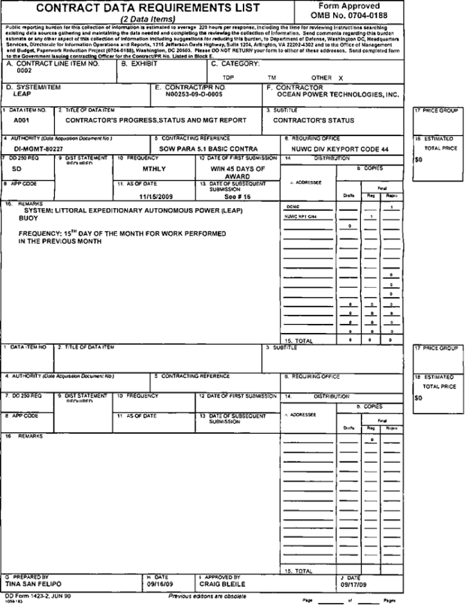
| CDRL A0001 in accordance with the Statement of Work Section 5.1 on basic contract for Contractors Progress, Status and Management Report. Delivery dates: 15th day of the month for work performed in the previous month. Deliveries shall go to the Contracting Officer’s Representative. Craig Bleile at craig.bleile@navy.mil. Referenced in Section J. | ||||||||||
| FOB: Destination | ||||||||||
| ESTIMATED COST | $ | 0.00 | ||||||||
| FIXED FEE | $ | 0.00 | ||||||||
| TOTAL EST COST + FEE | $ | 0.00 | ||||||||
Section C — Descriptions and Specifications
STATEMENT OF WORK
Littoral Expeditionary Autonomous Power (LEAP) Buoy
IDIQ Contract Task Order 1
Statement of Work
IDIQ Contract Task Order 1
Statement of Work
Prepared For:
Ocean Power Technologies Inc. (OPT)
1590 Reed Road
Pennington. NJ 08534
Ocean Power Technologies Inc. (OPT)
1590 Reed Road
Pennington. NJ 08534
Prepared By:
NIJWC Division, Keyport
NIJWC Division, Keyport
TABLE OF CONTENTS
1.0 Introduction
|
5 | |||
1.1 Background
|
5 | |||
1.2 Program Overview
|
6 | |||
1.3 Scope
|
6 | |||
2.0 SYSTEM REQUIREMENTS
|
8 | |||
2.1 System Functional Requirements
|
8 | |||
2.2 Subsystem Requirements
|
8 | |||
2.3 Environmental Requirements
|
8 | |||
3.0 STATEMENT OF WORK
|
9 | |||
3.1 Task 1: LEAP VDST Requirements Analysis and Definition
|
9 | |||
3.2 Task 2: Systems Engineering Planning
|
9 | |||
3.3 Task 3: Design LEAP VDST Subsystems
|
9 | |||
3.3.1 Design PowerBuoy Power Take-Off (PTO) Subsystem
|
9 | |||
3.3.2 Configure FIE Radar System
|
10 | |||
3.3.3 Design Vessel Detection Processor
|
10 | |||
3.3.4 Design [**] Network Interface Processor
|
10 | |||
3.3.5 Configure [**] System
|
10 | |||
3.4 Task 4: Build and Test Prototype Subsystems
|
10 | |||
3.4.1 Build and Test PowerBuoy PTO Subsystem
|
10 | |||
3.4.2 Build and Test HF Radar System
|
10 | |||
3.4.3 Build and Test Vessel Detection Processor
|
11 | |||
3.4.4 Configure and Test [**] Network Interface Processor
|
11 | |||
3.4.5 Configure and Test [**] System
|
11 | |||
3.5 Task 5: Preliminary Subsystem Testing
|
11 | |||
3.6 Task 6: Test Data Reduction and Analysis
|
11 | |||
3.7 Task 7: Real-Time System Transition Studies
|
11 | |||
3.8 Task 8: Follow-on Work
|
12 | |||
3.9 Task 9: Program Management
|
12 | |||
4.0 DELIVERABLES
|
13 | |||
4.1 Documentation
|
13 | |||
5.0 Government Furnished Items
|
14 | |||
5.1 Government Furnished Information (GFI).
|
14 | |||
5.2 Return of Government Furnished Items.
|
14 | |||
6.0 Deliverables
|
15 | |||
7.0 Special Conditions
|
16 | |||
7.1 SB1R Phase 111
|
16 | |||
7.2 SBIR Data Rights
|
16 | |||
7.3 Packaging and Marking
|
16 |
4
1.0 Introduction
1.1 Background
The Littoral Expeditionary Autonomous Power Buoy (LEAP) System is established to enhance the Navy’s
Anti-Terrorism/Force Protection (ATIFP) by providing persistent afloat and port maritime
surveillance in the near coast, harbors, piers and littorals worldwide. Waterborne threats, both
domestic and overseas, that include boats, swimmers, mini-subs, autonomous vehicles, and highly
lethal submerged mines form a substantial window of vulnerability for naval and civilian assets. A
viable system for protecting critical infrastructure and military assets from surprise maritime
terrorist attacks must include a system that detects and locates surface and subsurface threats.
There is a need for persistent and dependable, long-term operation of a surveillance network to
provide operational surface vessel tracking capabilities to prevent attacks from small, high-speed
vessels. This effort is intended to provide capabilities that bring persistent power at sea to
provide power to forward deployed sensors and communications equipment that can detect, track and
communicate target information in sufficient time in order to provide decision making capability
and operational execution against such threats.
[**]
1.2 Program Overview
The LEAP Program objective is to leverage a combination of existing technologies which includes a
wave energy conversion buoy, sensors and communications systems to improve force protection by
combining their features and capabilities into a single system. The systems integration shall be
achieved through the use of the [**] for integrating with sub-systems and to create a flexible and
net-centric architecture that can be distributed across multiple nodes and present a unified
Common Operating Picture (COP) to the operators.
The LEAP Program is based on the Ocean Power Technologies (OPT) PowerBuoy® wave energy conversion
system, which is an enabling technology for providing power to remote. at-sea sensors and
communications technologies. The operational experience and user inputs gained from ocean
demonstrations shall indicate those features to be implemented to increase the capability in the
near term and provide the cornerstone for further technological enhancements.
1.3 Scope
The scope of this Task Order 1 Statement of Work covers tasks to be performed during Year 1 (the
Base Year) of a proposed four-year program to develop a LEAP-based Vessel Detection System Testbed
(VDST). The VDST shall be deployed off the Atlantic coast of New Jersey and used to develop and
test hardware and software technology for real-time detection of vessels in its littoral coverage
area.
5
The VDST system architecture shall be based on:
| • | OPT’s PowerBuoy Wave Energy Conversion (WEC) technology, which provides a persistent at-sea buoy platform for HE radar transmitters | ||
| • | COTS multistatic HF radar equipment developed by [**], including at-sea transmitters and shore-based radar transceivers | ||
| • | The existing Rutgers Coastal Ocean Observatory Laboratory (COOL) facility | ||
| • | New radar signal processing and vessel detection algorithms to be developed by Rutgers Institute of Marine And Coastal Sciences, [**] | ||
| • | [**] which provides a Common Operating Picture to the user. |
6
Major tasks currently planned for this Task Order in the Base Year of the contract are:
| • | Development and laboratory testing of the PowerBuoy Power Take-off (PTO) subsystem |
||
| • | Deployment of first VDST shore station and HF radar transceiver | ||
| • | Development and testing of radar signal processing and non-real-time vessel detection algorithms based [**], using VDST shore station in conjunction with an existing radar shore site | ||
| • | Initial investigations of [**] and signal processing algorithms |
7
2.0 SYSTEM REQUIREMENTS
2.1 System Functional Requirements
The LEAP Vessel Detection System shall:
| • | Detect small surface vessels within its coverage area | ||
| • | Provide vessel detection reports to the [**] using standard communications protocols and message formats | ||
| • | Meet applicable environmental requirements | ||
| • | Support extended deployment lifetimes and 24/7 operation | ||
| • | Be scalable to large coverage areas. |
2.2 Subsystem Requirements
Detailed requirements for each major LEAP VDST subsystem shall be developed under Task 1,
Requirements Analysis and Definition. Subsystem requirements shall be documented in deliverable
reports as defined in Institute of Electrical & Electronics Engineers, Inc. (IEEE) Standard 1220
processes, such as System Requirements Specifications (SRS) and Interface Control Documents
(ICD).
2.3 Environmental Requirements
Environmental requirements shall be defined separately for at-sea and onshore subsystems.
8
N00253-09-D-0005
0001
Page 9 of 21
0001
Page 9 of 21
3.0 STATEMENT OF WORK
3.1 Task 1: LEAP VDST Requirements Analysis and Definition
| • | Define detailed system requirements |
| • | Vessel detection parameters and probabilities | ||
| • | Detailed environmental requirements | ||
| • | Shore station infrastructure | ||
| • | Deployment and recovery infrastructure | ||
| • | Communications network infrastructure | ||
| • | Extended lifetime and deployment area considerations | ||
| • | Integration with [**] and other Navy/Coast Guard (CG) systems |
| • | Define detailed program objectives and test requirements |
| • | Develop phased VDST implementation plan | ||
| • | Develop detailed test plans | ||
| • | Define post-processing data analysis and management methods | ||
| • | Establish performance objectives |
3.2 Task 2: Systems Engineering Planning
The contractor shall use a formal process development methodology to plan and control all aspects
of system development. The methodology used shall be tailored from the requirements of IEEE Std
1220-2005. The contractor team shall develop a System Engineering Management Plan in accordance
with IEEE 1220 including:
| • | Interface definitions | ||
| • | Subsystem functional requirements | ||
| • | Hardware/Software (NW/SW) tradeoffs | ||
| • | Commercial Off The Shelf (COTS) vs. custom design | ||
| • | Applicability of existing equipment/facilities | ||
| • | Real-time system and transition requirements | ||
| • | Requirements documents |
3.3 Task 3: Design LEAP VDST Subsystems
The contractor shall investigate technical trade-offs. conduct laboratory investigations and
develop detailed hardware/software designs for each subsystem, as follows. Design documents shall
be developed in standard and contractor formats.
3.3.1 Design PowerBuoy Power Take-Off (PTO) Subsystem
| • | Develop PTO requirements specification | ||
| • | Develop PTO subsystem design specifications | ||
| • | Conduct PTO conceptual design and trade-offs | ||
| • | Develop detailed H W/SW designs | ||
| • | Develop manufacturing drawings |
N00253-09-D-0005
0001
Page 10 of 21
0001
Page 10 of 21
| • | Conduct design reviews 3.3.2 |
Configure HF Radar System
| • | Procure COTS [**] (1 unit), to be deployed at first VDST shore station. This consists of radar transmitter, receiver and radar signal processor. | ||
| • | Procure and install COTS [**] (1 unit) | ||
| • | Identify potential locations for radar systems | ||
| • | Procure and install COTS [**] Software Package [**] (1 unit), to be deployed at first VDST shore station | ||
| • | Procure COTS [**] (1 unit), to be deployed on PowerBuoy platform |
3.3.3 Design Vessel Detection Processor
| • | Define and optimize threshold levels for vessel detection | ||
| • | Define and optimize background noise levels for vessel detection | ||
| • | Define and optimize integration times for vessel detection |
3.3.4 Design [**] Network Interface Processor
| • | Define host and network requirements | ||
| • | Define LEAP VDST interface | ||
| • | Define [**] protocol and network interfaces | ||
| • | Evaluate Government Furnished (GFI) Software used in [**] and CG systems | ||
| • | Design [**] message processing SW | ||
| • | Design [**] network protocol/interface processing SW |
3.3.5 Configure [**] System
| • | Configure [**] system for LEAP testing using COTS I-IW and GFI SW |
3.4 Task 4: Build and Test Prototype Subsystems
3.4.1 Build and Test PowerBuoy PTO Subsystem
| • | PTO manufacturing and procurement | ||
| • | Perform acceptance testing of PTO components | ||
| • | Perform preliminary PTO system integration | ||
| • | Conduct PTO laboratory testing and measure power generation capacity | ||
| • | Perform redesign/rework as needed |
3.4.2 Build and Test HF Radar System
| • | Install and calibrate first High Frequency (HF) radar system at shore station | ||
| • | Configure and integrate [**] transmitter electronics |
N00253-09-D-0005
0001
Page 11 of 21
0001
Page 11 of 21
3.4.3 Build and Test Vessel Detection Processor
| • | Test and analyze performance of vessel detection processor, based on bistatic operation using first VDST shore station and existing Rutgers shore site | ||
| • | Examine environmental conditions (sea state, radio interference, external noise) impacting performance of VDST | ||
| • | Plan development for real time VDST |
3.4.4 Configure and Test [**] Network Interface Processor
| • | Configure standard Wintel host and network interfaces | ||
| • | Develop and test LEAP VDST interface | ||
| • | Develop and test [**] protocol and network interfaces | ||
| • | Integrate GFI SW as needed | ||
| • | Develop and test [**] message processing SW | ||
| • | Develop and test [**] network protocol/interface processing SW | ||
| • | Software integration and standalone testing |
3.4.5 Configure and Test [**] System
| • | Procure COTS HW (Wintel, Sun server for Common Joint Mapping Tool Kit) | ||
| • | Install GFI [**] SW | ||
| • | Preliminary SW testing and familiarization |
3.5 Task 5: Preliminary Subsystem Testing
| • | Radar/VDST integration testing | ||
| • | VDST/[**] integration testing | ||
| • | [**] integration testing | ||
| • | VDST/[**] integration testing |
3.6 Task 6: Test Data Reduction anti Analysis
| • | Correlation of VDST results with known shipping traffic | ||
| • | Correlation of VDST results with known ambient wave climate | ||
| • | VDST performance analysis including detection and false alarm probabilities and dependence on ambient wave/wind climates | ||
| • | Identify and resolve anomalies |
3.7 Task 7: Real-Time System Transition Studies
| • | Develop real-time vessel detection system architecture | ||
| • | Investigate technical trade-offs in conversion from offline to real-time signal processing and vessel detection algorithms | ||
| • | Investigate signal processing partitioning between VDST and [**] trackers and data fusion framework | ||
| • | Plan phased implementation of real-time system |
N00253-09-D-0005
0001
Page 12 of 21
0001
Page 12 of 21
3.8 Task 8: Follow-on Work
| • | Develop recommendations for follow-on work | ||
| • | Identify key performance drivers and operational improvements | ||
| • | Identify production transition issues and risk mitigation strategies |
3.9 Task 9: Program Management
The contractor shall designate a project manager who shall be responsible for the control and
coordination of all work performed on this delivery order. The contractor shall provide the project
manager’s name, in writing, to the PCO within 7 days after issuance of delivery order.The
contractor PM shall establish and maintain a program plan, schedules, budgets, work
assignments/allocations, and delivery plans.
N00253-09-D-0005
0001
Page 13 of 21
0001
Page 13 of 21
4.0 DELIVERABLES
4.1 Documentation
Documentation deliverables are shown in Table 1. These deliverables may be revised as necessary in
accordance with the IEEE Std 1220 process development methodology to be used in the proposed
program.
B001
|
System Specification | One time | ||
B002
|
System Interface Specification | One time | ||
B003
|
Subsystem Specification | One per subsystem | ||
B004
|
Subsystem Interface Specifications | One per subsystem | ||
B005
|
Subsystem Integration Test Plan | One time | ||
B006
|
System Test Plan | One time | ||
B007
|
System Test Results | One time | ||
B008
|
Program Status Report | bimonthly | ||
B009
|
Final Technical Report for Task Order I | One time |
Table 1: Deliverable Documentation
N00253-09-D-0005
0001
Page 14 of 21
0001
Page 14 of 21
5.0 Government Furnished Items
5.1 Government Furnished Information (GFI).
The contractor shall identify and request any Government Furnished Information (GFI) deemed
necessary to complete SOW requirements. The Government will assist the contractor in
obtaining information. This includes technical manuals, training materials and information.
drawings, specifications. procedures, processes, and quality system documents required for
the performance of engineering, logistics. and technical support. Software related to the
[**] will be made available for use on contractor hardware to assist in integration
tasking, if the contractor should desire. The government shall assist in loading and
configuring [**] software at Keyport. Wa. As required.
5.2 Return of Government Furnished Items.
All GFI and GFE provided to or acquired by the contractor shall be returned to the
Government upon completion of assigned tasking.
N00253-09-D-0005
0001
Page 15 of 21
0001
Page 15 of 21
6.0 Deliverables
The Contractor shall provide data in accordance with the Statement of Work (SOW) and DD Form
1423, CDRLs, as specified under each task order issued under this contract. The base SOW
contains the following deliverable data:
| CDRL | SOW PARA | TITLE OF DATA ITEM | FREQUENCY | |||||
A001
|
5.1 | Contractors Progress, Status and Management Report | 15th day of the month for work performed in the previous month. | |||||
Documentation shall be delivered to the Government in MS Office soft copy format and hard copy
using Contractor format. If unable to submit electronically, data shall be provided by mail to:
Craig M. Bleile. NAVSEA KPWA 44, 610 Dowell Street, Keyport, WA 98345-7610.
N00253-09-D-0005
0001
Page 16 of 21
0001
Page 16 of 21
7.0 Special Conditions
The following special conditions shall apply to the contractor in the performance of the
tasks under this IDIQ contract.
7.1 SBIR Phase III
The LEAP technology was originally developed under the Small Business Innovation Research
(SBIR) Program. specifically Topic Number N00-116. entitled Modular 100kW Wave Powered
Electric Generator (SBIR Phase I Contract Number N00014-01-M-0041 and Phase 11 Contract
Number N00014-02-C-0034). The work to be performed under this IDIQ contract extends the
work performed under these prior SBIR Phase I and Phase II contracts, and as such is
accorded all rights of an SBIR Phase III funding agreement.
7.2 SBIR Data Rights
This contract incorporates the following clause:
DFARS 252.227-7018 Rights In Noncommercial Technical Data And Computer
Software—Small Business Innovation Research (SBIR) Program (JUN 1995) (Also
applies to STTR programs)
7.3 Packaging and Marking
Preservation, packaging, packing and marking of all deliverable contract line items
shall conform to normal commercial packing standards to assure safe delivery at
destination.
All reports. briefs, technical documents, etc. submitted to the Government under
this contract should contain the following legend:
SBIR or STTR DATA RIGHTS
Topic Numbers:
|
N95-074 and N00-116 | |
Contract No.:
|
N00014-09-C-01 15 | |
Contractor Name:
|
Ocean Power Technologies, Inc. | |
Contractor Address:
|
1590 Reed Road; Pennington, NJ 08534-5010 |
The Government’s rights to use, modify, reproduce, release, perform, display, or disclose
technical data or computer software marked with this legend are restricted as provided in
paragraph (b)(4) of DFARS 252-227-7018. Rights in Noncommercial Technical Data and
Computer Software—Small Business Innovative Research (SBIR) Program.
N00253-09-D-0005
0001
Page 17 of 21
0001
Page 17 of 21
Section E — Inspection and Acceptance
INSPECTION AND ACCEPTANCE TERMS
Supplies/services will be inspected/accepted at:
| CLIN | INSPECT AT | INSPECT BY | ACCEPT AT | ACCEPT BY | ||||
0001
|
Destination | Government | Destination | Government | ||||
0002
|
Destination | Government | Destination | Government |
N00253-09-D-0005
0001
Page 18 of 21
0001
Page 18 of 21
Section F — Deliveries or Performance
DELIVERY INFORMATION
| CLIN | DELIVERY DATE | QUANTITY | SHIP TO ADDRESS | UIC | ||||
0001
|
POP 25-SEP-2009 TO 24-SEP-2010 |
N/A | NAVAL UNDERSEA WARFARE CENTER RECEIVING OFFICER ATTN: DIVISION KEYPORT SUPPLY OFFICER BLDG 893 610 DOWELL STREET KEYPORT WA 98345-7610 360 396-2776 FOB: Destination |
N00253 | ||||
0002
|
POP 25-SEP-2009 TO 24-SEP-2010 |
N/A | N/A FOB: Destination |
N00253-09-D-0005
0001
Page 19 of 21
0001
Page 19 of 21
Section G — Contract Administration Data
ACCOUNTING AND APPROPRIATION DATA
AA: 1791319 75XZ 253 SASLM 0 068342 2D 527530 9D90A000C0NO
AMOUNT: $2,449,835.99
CIN 915214260001: $2,449,835.99
AMOUNT: $2,449,835.99
CIN 915214260001: $2,449,835.99
| CLIN | JOB ORDER | FUNDS EXP. DATE | FUNDED QTY | FUNDED AMT | ||||||||
0001
|
0195SBR | 30-SEP-2009 | 1.00 | $ | 2,449,835.99 | |||||||
CLAUSES INCORPORATED BY FULL TEXT
HQ G-2-0007 INVOICE INSTRUCTIONS (NAVSEA) (OCT 2006)
(a) In accordance with the clause of this contract entitled “ELECTRONIC SUBMISSION OF
PAYMENT REQUESTS" (DFARS 252.232-7003), the Naval Sea Systems Command (NAVSEA) will
utilize the DoD Wide Area Workflow Receipt and Acceptance (WAWF) system to accept
supplies/services delivered under this contract. This web-based system located at
https://wawf.eb.mil provides the technology for government contractors and authorized
Department of Defense (DoD) personnel to generate, capture and process receipt and
payment-related documentation in a paperless environment. Invoices for supplies/services
rendered under this contract shall be submitted electronically through WAWF. Submission of hard
copy DD250/invoices may no longer be accepted for payment.
(b) It is recommended that the person in your company designated as the Central
Contractor Registration (CCR) Electronic Business (EB) Point of Contact and anyone
responsible for the submission of invoices, use the online training system for WAWF at
http://wawftraining.com. The Vendor. Group Administrator (GAM), and sections marked
with an asterisk in the training system should be reviewed. Vendor Quick Reference Guides
also are available at http://acquisition.navy.mil/navyaos/content/view/ful1/3521/.
The most useful guides are “Getting Started for Vendors” and “WAWF Vendor Guide”.
(c) The designated CCR EB point of contact is responsible for activating the company’s
CAGE code on WAWF by calling 1-866-618-5988. Once the company is activated. the CCR EB point of
contact will self-register under the company’s CAGE code on WAWF and follow the instructions
for a group administrator. After the company is setup on WAWF, any additional persons
responsible for submitting invoices must self-register under the company’s CAGE code at
https://wawf.eb.mil.
(d) The following information regarding invoice routing is provided for completion of the
invoice in WAWF:
| WAWF Invoice Ty pe | Cost Voucher | |
Pay DoDAAC
|
HQ0337 | |
Admin DODAAC
|
S3915A | |
Inspection
|
Desination | |
Acceptance
|
Desination | |
Fast Pay (FAR 52.213-1 required)
|
No |
N00253-09-D-0005
0001
Page 20 of 21
0001
Page 20 of 21
| WAWF Invoice Ty pe | Cost Voucher | |
Ship To Code (DoDAAC) |
N00253 | |
LPO DODAAC (if applicable) |
*** | |
DCAA DODAAC (if applicable) |
HAA310 | |
Applicable CLIN/SLIN |
0001 |
For detailed instructions on submitting documents in WAWF, please review the information posted at
the following link:
http://acquisition.navy.mil/rda/home/acquisition_one_source/ebusiness/don_ebusiness_solutions/wawf_overview/vendor_information
Attachments created in any Microsoft Office product may be attached to the WAWF invoice, e.g.,
backup documentation, timesheets. etc. Maximum limit for size of each file is 2 megabytes. Maximum
limit for size of files per invoice is 5 megabytes.
(e) Before closing out of an invoice session in WAWF, but after submitting the document(s), you
will be prompted to send additional email notifications. Click on “Send More Email Notification”
and add the acceptor/receiver email addresses noted below in the first email address block, and add
any other additional email addresses desired in the following blocks. This additional notification
to the government is important to ensure that the acceptor/receiver is aware that the invoice
documents have been submitted into WAWF.
Send Additional Email Notification To:
Receiptcontrol.nuwckpt.fct@navy.mil
Tariq.al-agba@navy.mil
Craig.bleile@navv.mil
Tariq.al-agba@navy.mil
Craig.bleile@navv.mil
(f) The contractor shall submit invoices for payment per contract terms and the government
shall process invoices for payment per contract terms.
(g) For specific questions regarding your invoice please contact the Keyport Vendor Pay group
at (360) 315-8500 or at vendorpay.nuwckpt.fct@navy.mil. If you have any questions regarding WAWF,
please contact the WAWF helpdesk at the above 1-866 number or the NAVSEA WAWF point of contact
Margaret Morgan at (202) 781-4815 or margaret.morgan@navy.mil.
(End of Text)
N00253-09-D-0005
0001
Page 21 of 21
0001
Page 21 of 21
Section J — List of Documents, Exhibits and Other
Attachments LIST OF ATTACHMENTS
Attachment
1. Contract Data Requirements List (CDRL) A0001